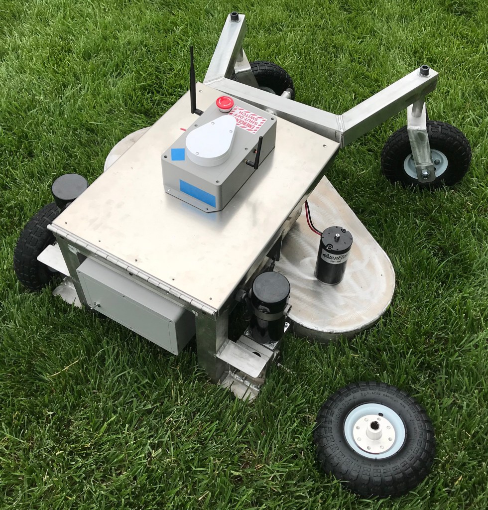
What could have been the ignition source for a Kansas grass fire.
If you look closely at the charts in the previous post, you’ll notice they end quite abruptly. The picture above shows why.
I have the robot mower configured so the blades only turn on when you hold the rudder stick to the right. The stick is spring loaded, so letting go of it returns it to center, deactivating the blades.
A typical shrub out in the field. Most were about 18in tall.
The field I was testing in had several large shrubs in it. One of my goals in the field was to push the envelope on what the mower was capable of cutting through, so I let it mow over several of them in autonomous mode. However, there was a particularly large shrub in the robot’s path, and so I decided to turn the mower blades off by releasing the rudder stick.
As expected, the blades stopped. But the robot stopped moving, too. This was curious: the robot should have continued driving. So I pressed the emergency stop button on the robot to immobilize it, and walked over to the truck where I had Mission Planner running on my laptop.
A screenshot of Mission Planner telemetry log after I returned to the truck. The reported voltage is 12.50V.
The Mission Planner screen was frozen as if it wasn’t receiving telemetry from the robot. It took me a few minutes to realize that the issue wasn’t Mission Planner or my laptop radio: it was that the robot wasn’t sending telemetry. And even more curiously, the voltage reading on my SLA batteries said 12.50V. I was worried that I’d really fried my batteries, so I walked back over to the robot to investigate.
Opening the battery bay I found a slight amount of smoke and that awful burnt plastic smell from melted wire insulation. But other than that everything seemed fine. There wasn’t a smoldering fire inside the robot. The batteries weren’t hot to the touch.
At first I chalked it up to too much current running through the wires. The robot uses 120A at peak current, and at those levels even a small amount of resistance could cause the wires to heat up a lot. Perhaps the wires just got hot enough to melt the insulation and came into contact right at the moment I decided to shut the mower blades off?
One of the melted wires. The yellow blob on the end is a portion of a Posi-Lock.
This just so story didn’t sit well with me. What an awful coincidence that the wires failed at exactly the same moment I was shutting off the motors, especially after the robot ran fine for five minutes prior. Why didn’t they fail earlier?
Additionally, why didn’t the exposed wire conductors fuse together after they came into contact? I’ve heard of people using SLA batteries smaller than mine to spot weld 18650 battery tabs together. The wires were really close together, but weren’t touching when I opened the battery bay. And the wire strands don’t seem to be melted judging from the picture above. Which was extraordinarily lucky, given how bad that could have been.
I did have enough sense to put a 100A fuse on my batteries. It seemed logical that the fuse was what saved my bacon. But using the multimeter to test the fuse revealed that it was not, in fact, blown. At this point I was completely bewildered. I thanked the good Lord that the robot hadn’t turned into a massive lead acid fireball, made sure all my batteries were all disconnected, packed up, and went home.
I’m sure readers are ready to scold me for all of the janky things going on in my battery bay, and I certainly deserve that criticism. My mantra is make it robust, and I definitely did not live up to that standard with my wiring. Below is a full picture of the battery bay.
The robot mower battery bay. How many janky things can you spot?
I have my own list of janky things in here that I intend to fix. What do you see that is janky? Feel free to comment below!
In the next post, I’ll explain what I think went wrong, and the improvements I’m going to make to mitigate the problem and eliminate all the redneck wiring I’ve got going on.
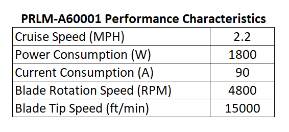
I didn’t spend much time in the field testing the robot mower, but the little time I did spend gave me a treasure trove of information about how the robot mower performs. Below are some high-level measures.
Performance characteristics for the robot lawn mower in the field.
I set the robot cruise speed to 1m/s or 2.2mph. I’ve run the robot mower faster in manual mode, but for obvious safety reasons, a moderate walking pace seemed best. If the robot gets out of control, I want to be able to catch it.
I am using a Mauch PL-200-HV current sensor on the robot. The sensor is connected to the positive terminal on my batteries, so it reports the total current used by robot: sensors, drive wheels, mower deck motors, etc. Once the mower is spooled up, current consumption levels out at about 90A.
Current consumption used by the robot mower.
The first portion of the graph above is the robot mower operating autonomously without the deck motors turned on. The huge spike is when the deck motors get turned on. It’s curious it says the peak is 196A: the PL-200-HV is only rated for 200A. I wonder if the spike was actually larger than shown, but due to its current rating, the sensor only reported ~200A.
There is a surprising variability to the amount of current used by the deck motors. In the garage, the deck motors would use 46A +/-1A. It was kind of impressive how steady current consumption was. But throw some grass under the robot and you get a ton more variability. Current consumption for the whole robot varies from 65A to 120A with the deck motors on.
Grass is typically pretty homogenous, even out in the field, so this was unexpected. I went and reviewed the logs from my backyard, and they look about the same. Even controlling for pivot turns at the end of a pass, the current consumption is all over the place.
Current consumption versus steering commands. Each spike on the green line is the robot mower making a pivot turn at the end of a pass.
It does appear to dip a little with each turn, but only ~15A. Maybe I’m reading into it too much. There were some small shrubs and some pretty gnarly crab grass plants out in the field. The current variation might just be the mower running over those things.
I also wanted to see how much the battery voltage dropped when running the deck motors in a real-world situation.
Battery voltage level before and after the mower deck motors were turned on.
I made sure all four of my batteries were individually fully charged before going to the field. But any way you cut it, asking 90A out of four 35Ah SLA batteries is pushing it. With the deck motors on, the nominal battery voltage drops to 20V.
I toyed with the idea of using lithium ion or similar batteries from the start when designing the robot mower. But they’re pretty pricy, and for the time being, SLA batteries will work well enough for field testing. The four 35Ah SLA batteries were less than $200, so I can afford to run them like a rented mule.
To get the total power consumed by the robot you need two things: current consumed and the voltage level when it was consumed. Mission Planner will do the math for you by multiplying the current and voltage at each time step and then adding them up for a total energy consumed graph.
A running total of the energy used by the robot over time. Find the slope of that line and you’ve got the average power consumption over that time period.
Unfortunately, Mission Planner won’t differentiate that graph for you so you can see what the power consumption was at any given time. But if we assume the power consumption is linear over the five minute time interval above, we can estimate it.
A simple way to calculate the power consumption for the robot mower.
This number is encouraging. I’ve seen the drive motors on typical electric riding mowers consume more than 1kW by themselves, excluding the deck motors. I need to do some more testing to see how efficient the robot mower is on less flat terrain. But as you’d expect, there appear to be a lot of power savings to be had by getting rid of the guy riding the mower.
Regarding the blade motor rotation speed, there are two ways I can think of to estimate this. One way is based on the current consumed by each motor. Take that number to the motor performance charts and you can estimate rotation speed.
The other is to see at what frequencies the mower is vibrating at. Thanks to some new developments by the Ardupilot folks, this is a pretty straightforward task. If you can find the frequency where you get strong vibrations at, you can assume that’s the probably speed at which the motors are rotating.
The mower uses about 5A when running without the blade motors on. That means all three motors consume 85A, or each motor consumes 28A.
Performance curves for the AmpFlow E30-400 DC motor.
At 28A of current consumption, an E30-400 motor spins at 5100RPM, uses 540W of power and and achieves 1N·m or 0.74ft·lb torque. One of the big question marks in the robot mower design has been how well the motors would perform. It appears they’re just about perfect, operating right at the peak of its efficiency curve.
Speaking of efficiency, one thing I did notice about the deck motors was that even after a few minutes of operation, they were very hot to the touch. So hot I couldn’t keep my hand in contact without significant discomfort. Yes, I did try. I’m guessing they were north of 140°F.
Even if the motors are 79% efficient, that means that 21% of that 540W, or 113W, gets turned into waste heat. That’s a fair amount of heat to dissipate through a 5in long, 3in diameter cylinder by free convection. It might be worthwhile to come up with some kind of cooling fin to attach to the motor housing.
Ardupilot now has a feature that lets you analyze logs to see where vibration issues might exist. It looks at data recorded by your IMU and does a fast Fourier transform on the data to find frequencies at which you have high levels of vibration.
Using this method to estimate the motor rotation speed gives you several graphs that look like the one below.
The amplitude of vibration in the X, Y and Z directions on the robot mower across the frequency spectrum.
My understanding is that this graph gives you the strength of vibration at certain frequencies. I am unsure of the units on the Y axis. I think they’re m/s, but that seems awfully high. But then again, the mower deck is basically a giant vibratory table. I have no reason to believe they’re not accurate.
One thing that is interesting to note is that the amplitude of vibration is high in the X and Y directions across the spectrum, but less so in the Z direction. I think X is the forward to aft direction and Y is the left to right direction on the robot. So high levels of vibration along those axes makes sense when you think about a giant unbalanced motor rotating along an axis perpendicular to those two directions.
I’m assuming that all three motors are spinning at close to the same speed, but in reality, I’m sure they’re all off by some amount. I’m not sure how that affects the accuracy of this method of estimating the mower blade speed. Regardless, 4680RPM jives with the estimates obtained from the motor chart. The truth is probably somewhere in the middle, perhaps 4800RPM.
The calculation for blade tip speed with a motor rotation speed of 4800RPM and a blade length of 1ft.
15000ft/min is well below the 18000ft/min limit that manufacturers abide by. But judging from the good cut quality in the field, it might be possible run the motors slower. This would reduce the power we need to run the robot. AmpFlow makes a motor that is identical to the E30-400 that is a little bit shorter and uses less power. I might see if it would make sense to use this motor instead.
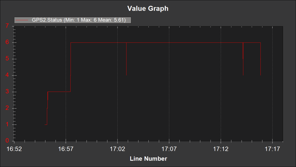
The fix status for the ZED-F9P GNSS module. 6 is RTK fixed.
I made some setting changes to the RTK GNSS modules based on some great comments I received a few posts back. I outlined those changes in this post. After that post, I made one additional change to the CFG-NAVSPG-DYNMODEL configuration item. I set it to 3 = Pedestrian.
The graph above shows the RTK fix status. The changes I made in that post resulted in a rock solid RTK fix. The little dips in RTK status were less than a second in duration. Thank you to Sean Smith and Frank Beesly for their valuable feedback!
The magnetometer performance was more or less garbage. I think a good portion of my cross track error is due to the compass variance corrupting an otherwise good position solution given by my wheel encoders and RTK GNSS.
Reviewing the telemetry logs, before I was even in autonomous mode, the EKF was reporting a marginal compass health reading. And the chart below tells you all you need to know about the rest of the compass performance.
The magnetometer’s reported Y magnitude versus the total current used by the robot.
The reported magnetic field strength jumps by 0.15 Gauss after you turn the deck motors on. It might be possible to zero this out in the software by finding the offsets when the deck motors are on, but I have so little confidence in the magnetometer at this point, it’s not worth the effort in my opinion. RTK GNSS yaw seems like a much more robust solution for heading.
Keen observers will notice something peculiar at the 17:16 mark on these graphs. More on that in the next post.
The robot mower making its first autonomous stripes on a field.
The past few Saturdays I’ve been playing with the robot mower in my backyard. It’s been fun manually driving it around my sprinkler well, flower beds, and garden. The fun ends a lot faster than I’d like: my push mower is 21in wide, but the robot mower is 36in wide, so it doesn’t take very many passes to get most of it mowed.
I’ve spent a lot of time in the backyard for two main reasons: firstly, I want to make sure the mower is safe before I take it somewhere it could hurt a bystander. And secondly, I want to make sure it doesn’t do an embarrassingly bad job at cutting grass.
Before I even took the mower out into the backyard, I ran it in my garage with the door down for a good hour or so to make sure the blades were installed securely. The first time I spooled it up was pretty scary. The garage is a giant echo chamber, and so it sounded a lot louder than when I had it running in the backyard.
Once I was satisfied it wasn’t going to vibrate apart, I maneuvered it into my backyard to see how it handled in manual mode, and how good of a job it did cutting my grass. Overall, it performed very well, making grass clippings without any difficulty. I did, however run into two issues:
The turnbuckle holding the deck to the chassis needs to be larger.
In manual mode, you can take turns pretty quickly, resulting in some large side forces on the turnbuckle eyes. These turnbuckles were only rated for 36lbf in tension and I wondered how well they’d hold up. Guess we know the answer to that question.
Locknuts are effective only if the locking portion of the nut is engaged with the threads.
While taking one of those fast turns in manual mode, I had a tire pop off. Yikes! Upon closer inspection, it turns out the nylon portion of the locknuts on the motor shaft were not actually threaded onto the shaft.
In my CAD model I had 1.5 threads engaged. Not great, but enough engagement to where I wasn’t worried about it. In reality, I didn’t get them threaded on all the way. I replaced both locknuts with a split lock washer and a jam nut.
These were good issues to discover in the backyard, where I could easily fix them without much embarrassment.
The field. A great view of the sky and a few weeks’ worth of grass growth to test the mower’s capabilities.
Satisfied that everything was working well, I loaded up and headed out to the field to try an autonomous mission. My backyard is great for manual mode, but it’s too small to run an autonomous mission.
It’s always good to have goals when you head to the field. For this field trip, I wanted to accomplish the following:
Practice getting the mower from my garage to the field. With four 35Ah lead acid batteries in the mower, it weighs close to 300lb now. Getting it from point A to point B is turning out to be an art in and of itself.
I made some changes to the ZED-F9P RTK GNSS settings based on comments made on a prior post. I wanted to determine if these changes helped or hurt my ability to maintain an RTK fix.
Being in a field with tall grass, I also wanted to push the envelope and see what the mower could cut effectively. The homogeneous fescue in my yard isn’t that difficult to cut.
Collect some general data about the mower’s performance. How much power does it actually use? How hot do the motors get after running for a while? How well does it mow autonomously?
Before I was using the mower deck, I only had two batteries in the battery bay. Loading and unloading isn’t too bad in this scenario: you can pretty easily drive the mower up the ramps and into the bed of my truck. With the other two batteries installed, that process becomes a little sketchier.
The wheel chair gearmotors have a neat little quarter-turn mechanism that disengages the output shaft from the rest of the gear train and lets the wheels spin freely, so I used this feature to push the mower up the ramps and into the bed of my truck. It’s too difficult to precisely maneuver the mower up the ramps and into the bed using the RC transmitter with the added battery weight.
Once in the field, I drove the mower out a safe distance away from the street to let it start working on an RTK fix. I wasn’t worried about absolute position, so I had the RTK base station configured to survey-in its location and used whatever it eventually settled on.
The first autonomous mission for the robot mower.
After I had an RTK fix, it was off to the races. I made a mission that was approximately a 100ft square and planned passes that were spaced 30in apart.
I configured channel 4 on my transmitter, the rudder stick, to control the power to my mower blades. This way it functioned as a dead man switch: if I let go of it, it would spring back to the neutral position. I designed relays inside the power enclosure to engage when the stick was held to the left. To keep the mower blades on, the stick must remain in that position.
After the mower made a few passes autonomously, I turned the blades on. That’s what you see in the video at the top of this post.
The cross track error was pretty large. You can see my tape measure lying in the grass for scale.
If the mower had maintained its position perfectly during the mission, each pass should have overlapped 6in because the mower deck is 36in wide and each pass was spaced 30in apart. Unfortunately, the mower’s position floated around by a fair amount. The un-mowed portions of the field are a result of this position error, which I’ve heard referred to as cross track error.
In some areas, the width of un-mowed grass was as large as 16in. This was a little disappointing. On average it was closer to about 8in. I need to find ways to improve the mower’s position estimate, so I don’t have to tighten up the spacing between passes.
The robot was using the magnetometer for heading, and you can see in the video that after each 180° pivot turn, the mower weaves a little bit as it tries to figure out its heading again. I intend to run another mission in the field soon with the magnetometers disabled to see if this improves the heading. Long term, I will look into using an additional RTK GNSS receiver to estimate the robot’s yaw.
This post is already pretty long, so I’ll make a separate one to review the logs and performance metrics I wanted to measure out in the field.
Several comments on my post about the RTK GNSS results I experienced in the parking lot have made me reconsider how good my RTK fix really was. I was able to get a fix pretty easily, but it was fragile, and would frequently drop back to float without any apparent change in the environment.
When searching for ways to improve the robustness of the RTK fix, I came across this very comprehensive discussion about u-Blox receiver settings. The consensus I gathered from the discussion was that there are two configuration changes on the ZED-F9P boards that can really improve your RTK fix robustness: tightening up the elevation mask and increasing the signal to noise threshold.
To change these settings, I connected the ZED-F9P module via USB to my computer and then connected to it within the u-Center software. I then went to View > Generation 9 Configuration View. I double clicked on the Advanced Configuration on the left pane to show all the various configuration items.
You can use the CFG-NAVSPG-INFIL_MINELEV configuration item to set the elevation mask. This angle is measured from the horizon upwards. Satellites below this elevation are excluded from the navigation solution. The default is 10°, which I changed to 15°.
You can use the CFG-NAVSPG-INFIL_MINCNO configuration item to set the signal to noise ratio. The default is 6dbHz. I set mine to 35dbHz.
It was kind of a pain to remove the module from the robot, connect it to my laptop, change the settings, and then replace it in the robot, so I didn’t do any A-B testing on these values, although I may in the future. The 15° elevation mask and 35dbHz signal to noise values were recommended from the discussion linked to above.
I did do an A-B test on an aluminum foil ground plane to see how that would improve the fix quality.
An aluminum foil ground plane underneath the RTK GNSS antenna.
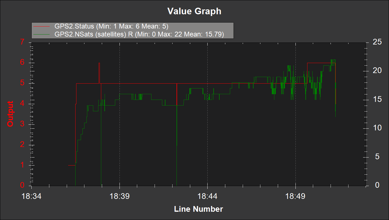
Below is the results with and without the ground plane. Initially I had the robot parked in my driveway under some trees, but after waiting more than 10 minutes for an RTK fix, I decided to drive the robot out in the street where there was a better view of the sky. Shortly thereafter, I got a fix.
The RTK GNSS performance without a foil ground plane. Left vertical axis is fix status where 6 = RTK fixed, and right vertical axis is the number of satellites seen by the receiver.
But with the foil ground plane, I was actually able to get a fix in my driveway under the trees. I drove the robot along my street at about 2:30 to see how robust the fix was. Much fewer hiccups, even with a more challenging environment.
The RTK GNSS receiver performance with a foil ground plane.
I ran the same mission down my street and back with and without the foil ground plane. The ability to keep the RTK fix with the foil was quite surprising. It’s definitely an improvement.
I will take these settings and foil ground plane to the parking lot soon and see how they perform.
Previously I was using GPS blending between a u-Blox NEO-M8N and a ZED-F9P. When the F9P had an RTK fix solution, all was well. But after losing the RTK fix, the position estimate reverted to the inferior M8N position solution.
So I conducted a few experiments to see if there was a way to get a better position estimate. I realized while tweaking parameters that the final position estimate is what we’re really trying to improve, not just the quality of our RTK fix from the F9P module. A better RTK fix will help our position estimate, but that’s only part of the equation.
Instead of feeding arbitrary coordinates into the base F9P module, this time I let it survey in with a precision of 2.5m and a time of 300s. I was surprised how close to the map imagery the survey in solution was. It was off by ~18in would be my guess.
I started by unplugging the M8N module, but unfortunately the compass is also powered by the 5V and GND pins on the data cable. So with both modules active, I set the GPS_AUTO_SWITCH parameter to 3, so that only the second GPS, the F9P, would be used.
This was a great way to test things because the flight controller was still logging the M8N data, but it wasn’t used for computing the robot’s position.
I was skeptical that this change would actually improve things because the F9P maintains an RTK fix only intermittently at best. But the results surprised me.
An excellent position estimate even with spotty RTK fixes.
The Ardupilot software has some magic in it (meaning code I don’t currently understand) that allows the rover to continue with high accuracy even without a GPS solution at times. I think the wheel encoders are helping significantly in this regard but I can’t say for certain.
And related, the blue line is the M8N position accuracy. It’s really terrible. At times it’s a parking stall width, about 2m, from the RTK fix position. In hindsight, I was corrupting a really good position solution by blending it with a solution that was always off by at least 2m.
I looped the same square mission about 20 times and placed screwdrivers on the asphalt at the center of the robot’s travel to mark it’s path and check its repeatability. I would estimate the path drifted ~4in over the 20 loops.
Here’s a picture of the first few loops of the mission. Even with some hiccups in the RTK fix solution, the overall position estimate is very good.
Several loops of the square mission. Even with some bad position data from the ZED-F9P module (green track) the position estimate (red track) is still rock solid.
I didn’t realize it until I started reviewing the logs, but the cell phone battery pack that I was using to power the base F9P module went to sleep after about 10 loops. That means no RTCM stream from the base, which means no RTK fix at the rover. But even without an RTK fix for 10 loops, the position solution was still very good.
The position solution with only a 3D Fix from the ZED-F9P. The red track is still solid.
In hindsight, the repeatability could be even better than ~4in that I was seeing if we could have intermittently re-established an RTK fix during that time.
Moral of the story: don’t ruin a really good answer (RTK fix) by averaging it with a really bad answer (3D fix).
Transporting the robot lawn mower. With the lead acid batteries installed, it weighs close to 300lb.
Late last year I traded in the Honda for a small truck. As I was designing the robot lawn mower it quickly became apparent that it wouldn’t fit in my little sedan. And even if it could, I’m not sure how I would load and unload a machine that weighs 300lb by myself.
I thought about taking it apart to transport it and then putting it back together in the field. But that is a very inefficient way to do business. The Honda had a great run, it was 16 years old and needed a new timing belt so I figured it was time to upgrade.
I’m a big fan of goals. For my afternoon in the parking lot, here was my to do list:
Figure out the best way to load and unload the robot mower into the truck.
Install my new wheel encoders and make sure they are working robustly.
Play with the RTK GPS modules.
Take the robot into some tall grass and see how it performs.
I realized that I have a few more things I need to bring to the field with the new robot lawn mower, so I updated my checklist of things to bring or do prior to leaving the house:
Cell phone with cellular data and enough storage space for several videos and photos
AA batteries for the RC transmitter
Make sure rover batteries are sufficiently charged
The toolbox with hex wrenches, adjustable wrench, and screwdrivers
Multimeter
Laptop with a good battery charge
Telemetry radio for the laptop
SD card, installed in the Pixhawk
RTK GPS receiver, antenna, and micro USB cable for power
Rechargeable batteries for RTK GPS base station
Prefetch any map data that will be needed in Mission Planner
Preplan any missions that may be needed and save the waypoint files
I typically would have gone to an actual field, but a parking lot offers some really nice geostationary markers that show up on satellite imagery: parking stripes.
The parking lot. Wide open skies, flat pavement, and geostationary lines. A perfect laboratory for implementing the RTK GPS modules.
My neighbor saw me using chunks of plywood to load the robot in the truck. He had some tailgate ramps he wasn’t using and let me borrow them for the day. I think I’m going to make him an offer for them. They were tremendously easy to use and transport.
The roof of a car makes for an awesome ground plane, so I decided to set up the RTK GPS base station on top of the truck. I noted which parking stall I was in and then found that same stall on the map imagery in Mission Planner and fed those coordinates to the ZED-F9P module.
To get a feel for how the RTK GPS was performing, I ran a circle mission.
A circle mission in the parking lot with RTK GPS.
On the map, the green line is GPS2, the position solution from the ZED-F9P module on the rover. The blue line is GPS1, the NEO-M8N module. My understanding is the red line is the EKF’s estimation of position after fusing sensor data with the GPS data.
The blue line is offset from the green line, even though their paths are pretty similar. I think this is because I arbitrarily selected the location of the base module. Essentially, I’m using two different origins: one for the RTK GPS versus whatever the M8N uses. This poses a problem when you lose the RTK fix.
An example of how the position solution from the EKF jumps when RTK fix is lost.
The ZED-F9P module doesn’t lose the RTK fix gracefully. It frequently goes from RTK fix to no solution. After a few seconds though it usually returns to an RTK fix. But once it’s lost, the EKF replaces the F9P position solution with the M8N’s solution. Which is off by a few feet.
You can see an example of this behavior in the picture above. The position is heavily weighted to the F9P solution, but once it’s lost, it jumps immediately to the M8N solution. Interestingly, when the F9P reports an intermediate solution such as 3D fix, the weighting behavior is more of an average between the two receivers.
I double checked my parameters and GPS_AUTO_SWITCH = 2, so the EKF should be blending solutions, not just using the most accurate solution of the two. And when both receivers are in 3D fix mode, that’s the behavior you see.
I have some questions based on these observations:
Is GPS blending really that useful? Maybe I should just ditch the M8N module all together. Whenever you have an RTK fix, it seems like this solution is so superior that the EKF basically ignores the M8N solution.
For GPS blending, would an additional RTK GPS help? The reported accuracies from two identical modules would be similar. Maybe the redundancy would help when an RTK fix is lost on one receiver.
Why does the EFK assume the robot’s position suddenly jumps? This is a rover, not a quadcopter. Especially when you have wheel encoders and an IMU, you should be able to assume that the robot’s position isn’t drifting significantly due to external disturbances, even if the GPS position jumps.
If we could eliminate the offset between the two solutions by using the same “datums” would that make the failover more graceful?
Some of those questions can be turned into experiments I can conduct the next time I’m out in the field:
Disable the NEO-M8N module. How does the robot respond when the ZED-F9P module loses an RTK fix?
Instead of arbitrarily setting the coordinates of the RTK base module, we can let it “survey in” to determine its location. This may eliminate some of the offset between the F9P and M8N position solutions.
We can measure the offset between the F9P and M8N solutions and then adjust the coordinates of the RTK base module to compensate. This would minimize the position jump between solutions when RTK fix is lost.
I also took the robot out into some taller grass to see how it would perform. You can see a video of it here. I also took a time-lapse of a typical grid run. Overall not bad, but for striping grass, it’s not good enough.
Going forward it looks like I will need ways to obtain a better position solution. I don’t think RTK GPS will get us there entirely. There are some exciting visual odometry solutions out there I may look into.
The prototype robot lawn mower, without the mower deck.
I was able to take the prototype robot lawn mower out for a drive this week. Watching the design drive off the computer screen and into my backyard has been immensely satisfying. Below are my notes from a day spent becoming better acquainted with the robot mower.
Vehicle Handling
Initially I wired the RC receiver straight into the Sabertooth so I could take it out for a drive. I’d forgotten how much smoothing the Ardupilot software adds to the control output. The robot was almost too responsive without it.
But overall, it handled wonderfully. I was almost able to drive up the curb from my street into my yard, but there wasn’t enough traction to get the back wheels up the curb. So far, so good!
However…
A scenario I hadn’t considered when I designed the robot mower.
After I got the Pixhawk wired up (more on that below) I ran a few autonomous missions and started tuning the steering and throttle PID values. At lower steering turn rates, I noticed the swivel caster wheels sometimes catch on the grass instead of swiveling, and the whole setup actually rotates about the center pin. The scenario in the picture above only occurred once, but I noticed the wheels getting hung up more than once.
When I was putting the robot together, I noticed the casters weren’t fabricated per my print. I had designed them with more offset between the wheel axle and the swivel axis. If this continues to be a problem, I’ll have them remade with a little extra offset so they swivel easier.
Wires
Getting the robot wired correctly was nerve wracking. I made a wiring diagram for the power enclosure and modeled up all the components and connections to make sure they fit, but I skipped this planning step for the Pixhawk enclosure. The amount of wires I had to route to the Pixhawk multiplied quickly:
5 wires from the drive wheel rotary encoders, a total of 10 for both motors.
4 Sabertooth control wires.
4 relay control wires.
6 wires for the Pixhawk power port.
2 emergency stop wires.
2 additional wires to power the servo rail on the Pixhawk.
I wasn’t expecting 23 wires needing to be routed to the Pixhawk enclosure, and making sure I didn’t get something wired incorrectly was nerve wracking.
And ultimately, I did wire something incorrectly. When I first powered the robot on, nothing happened, other than the Mauch BEC getting hot. And that’s never a good sign.
Turns out I had incorrectly wired the servo rail by swapping the + and – wires. Yikes. I eventually discovered the issue and fixed it, but not before learning a lot about the LM2576 voltage regulator I incorrectly thought was the issue.
Wheel Encoders
After I fixed the wiring, everything seemed to work, until I started running autonomous missions and had trouble getting the MAVLink Inspector within Mission Planner to show wheel encoder data. Initially I couldn’t even find the wheel encoder message. But after a few reboots it magically appeared. Not sure why it wasn’t visible from the start.
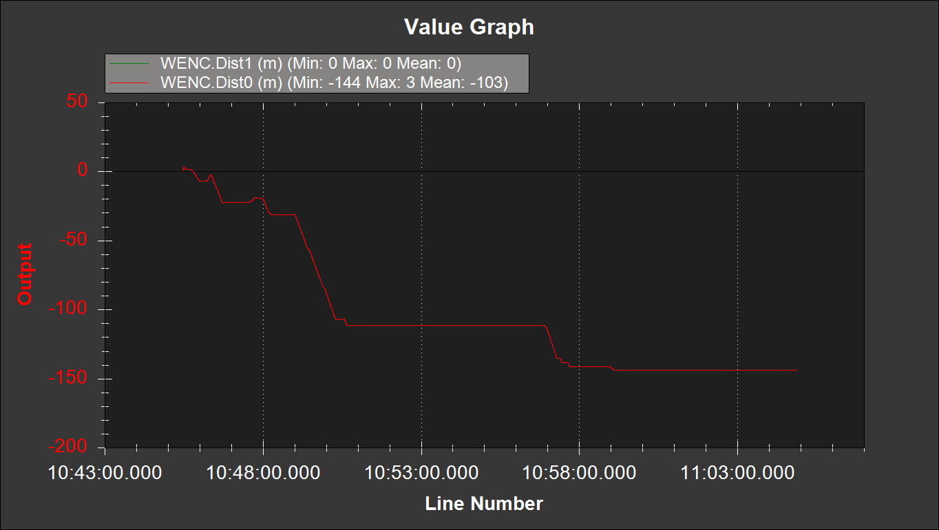
From the get-go, only the right wheel encoder was working. Below is WENC.Dist0 for the encoder on the left motor and WENC.Dist1 for the encoder on the right motor.
Wheel encoder total distance traveled as measured from the right and left wheel encoders. Note that WENC.Dist1 is 0.
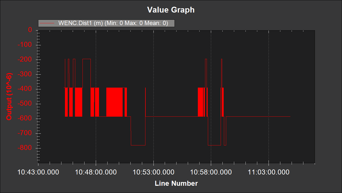
And below is what the graph for the right encoder by itself, WENC.Dist1 versus time, looks like.
The right encoder odometry data. Having watched the robot move around my backyard, I know this can’t be correct.
So to troubleshoot, I swapped the encoders. The idea is that WENC.Dist0 should look like the graph above and WENC.Dist1 should look like more like the first graph, with values much greater than 10E-6 and gradually increasing. This would isolate the issue to the encoder and not a settings, wiring, or Pixhawk error.
As an aside, having posted that graph I’m now wondering if the negative value means I have the A and B wires swapped. I was driving the robot forward mostly, so I would expect the values to be increasing, not decreasing. Regardless, at least the left encoder is obviously outputting some kind of useful data.
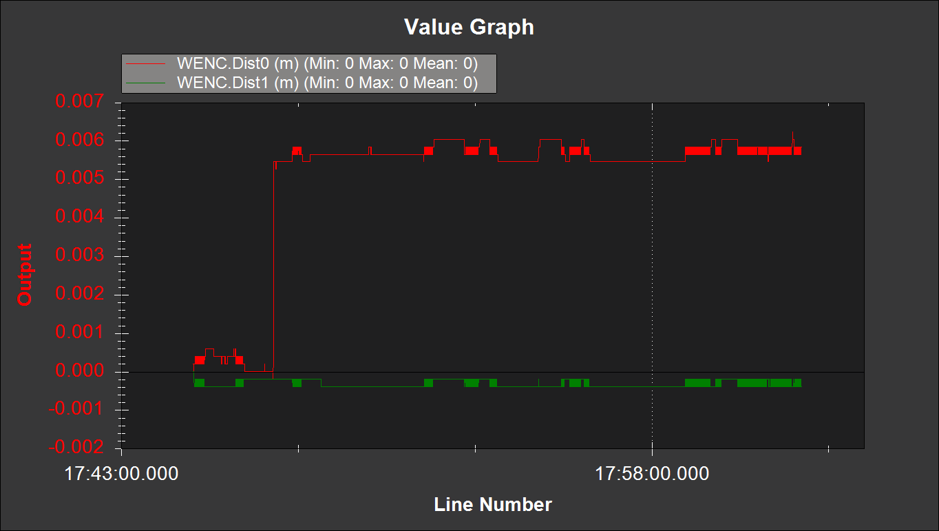
After swapping the encoders…
The WENC.Dist0 and WENC.Dist1 values after swapping the encoders.
Great, now they’re both broken!
I decided to call it quits after this because the sun was going down. I took the robot back into the garage and got the Arduino out to see what it said about the encoder output. Unfortunately it confirmed that the left encoder at a minimum was broken. The Arduino sketch counted pulses and only got up to 1 or 2 regardless of how much the wheel was rotating.
I remembered I had some 900CPR encoders I had purchased a while back and decided to see if I could get them to work with the Pixhawk. So I swapped the 32 CPR encoder with the 900 CPR encoder, and lo and behold, it started to work again.
All I can gather is that I must have fried one or both of the encoders with my wiring shenanigans. But it concerns me that one of the encoders was working at the start of the day and stopped working by the end of the day.
More to come once I get the mower deck assembled and installed. You can find a brief video of the rover doing an autonomous mission in my backyard here.
The Mr. Mower family is growing! Timing both a lull in the Kansas wind with a smile on Mr. Mower Jr.’s face for a picture is quite challenging.
The lack of activity here on MowerProject.com hasn’t been due to a lack of autonomous lawn mower development. This June we were blessed with a baby boy, and he has been taking up a lot of our time! Posting to the blog in the meantime has been difficult.
Juggling my 8 to 5, the mower project, and making time for Mr. Mower Jr. has been quite challenging. I owe a special thanks to my wonderful wife for letting me run errands for the project and work on it in the evenings. She is truly something special! Having her to bounce ideas off of and to encourage me along the way has been invaluable. I love you so much Mrs. Mower!
As I’ve done in the past, I find it’s good to set goals. Even if I don’t achieve them, they focus my mind and give me a sense of accomplishment and purpose as I work toward them. Below are some goals I have for the next few months.
Finish Procurement and Begin Assembly
I have all of the parts to build the prototype robot lawn mower except for two more SLA batteries and new enclosures for the electronics. The SLA batteries are so cheap that I think it’s worth a gamble on them instead of ponying up the $1,000+ I’d need for some good quality LiFePo4’s.
Once those items arrive I will start to wire up the enclosures and get the subassemblies put together. I will probably need to make another wiring diagram showing how everything connects and functions before I get too far along.
Support Fabrication of the Prototype Weldments
Originally I had planned to fabricate a lot of the robot lawn mower components myself. The idea was that it would be cheaper to purchase my own tools and make the parts myself. Unfortunately, that plan requires a lot of time, a resource I’m very much short on these days with Mr. Mower Jr. in the picture. The economics of paying someone to make the parts suddenly looks attractive again.
To this end I’ve found a local gentleman who is helping me make the weldments. I find myself over at his shop every week or so answering questions about the design, and working with him has been very productive. His feedback has been quite helpful in helping simplify and refine the design so that it is easy to fabricate.
Functional Testing
I have a litany of questions I need to get answered about the performance of the prototype before we even cut grass. A few questions I need to get answered:
How long can the mower run on four 12V, 35Ah SLA batteries?
How well does the prototype handle pivot turns?
How much current does the entire robot draw at typical operation?
We need to verify emergency stop and safety features function correctly.
How much air flow does the current mower deck and blade design create?
Once I’m satisfied the design adequately answers these questions, we can start cutting grass. Stay tuned for some pictures of the fabrication so far!
I may not be able to afford a Emlid Reach RS2, but I’ve got a cordless drill and an Amazon Prime account, dang it!
Putting my RTK base station on the mailbox works pretty good, but it takes a while to set it up and it’s not very robust. Using it in this manner results in a few problems:
The cell phone battery pack that I use to power to the receiver turns off after a while. I’m not sure if this is because the receiver only draws ~120mA of current and it doesn’t detect the receiver, or if it just times out. Either way, it’s quite annoying to discover the reason I can’t get an RTK fix or float is because the base station isn’t even on.
The neighbors getting their mail usually block enough satellite signals to cause the receiver to lose an RTK fix. Cars driving down the street will often affect the quality of reception, too. Unfortunately, I can’t pick up the mailbox and move it to a more favorable location.
The receiver and antenna are exposed to the elements. While I usually use them in good weather, I would like to be able to use them without having to worry about risking damage to the units from rain, wind, and the Kansas critters.
When I’m out testing in the parking lot there’s not an equivalent of my mailbox out there for me to set the receiver on. The roof of my car doesn’t count because it’s not geostationary. I’d like to have a way to repeatably locate the receiver when I’m testing in the parking lot.
Maybe I’m paranoid, but I’m always worried about some punk kid walking off with the base station module when it’s not within my line of sight. The punk kid I used to be in my teenage years would have done something malicious like that. It’d be great if I could make it a little bit more difficult to steal.
With these goals in mind, I decided it was time to build a real base station. One like the Emlid Reach RS2, but doesn’t cost me $1,899.
A Glorified Enclosure
The Emlid guys are geniuses. They basically took an RTK GNSS chip they can buy in bulk for $150 a piece, slapped it in a super nice thermoplastic case, developed an app that is more or less equivalent to U-Blox’s U-Center, and then stuck a price tag of $1,899 on it. I’m embarrassed I didn’t think of doing it myself.
They do offer some nice benefits with that $1,899 price tag, such as integral Wi-Fi and data logging capability, but in my humble opinion, those features aren’t worth what they’re charging. Realistically, I need a tripod, a mostly waterproof enclosure, a lead acid battery with a charger, and a cover for my GNSS antenna. Something like this:
My version of the Emlid Reach RS2.
I have a 12V lead acid battery and charger I stole from an old weed eater that I intend to use for this enclosure. The battery is rated for 3.6Ah, and according to the Ardusimple website, the board consumes 600mW at 5V, so 120mA of current. That would mean you could keep the Ardusimple board on for 30 hours. Not too shabby! I don’t know if they’re including the radio current consumption in those numbers, but even if it’s twice the 600mW they listed, we should be in good shape.
I’m still learning how to use these GPS modules, so I want to have access to the micro USB port that lets me communicate with them via U-Center. I found one of these cables for that purpose. I want to be able to interface with the board without opening the enclosure.
The guys that designed the Ardusimple boards were very forward thinking, and they made them such that you can power the board from any port or all the ports. The board has two micro USB ports, one for GPS data and the other for debugging the XBee radios. I don’t anticipate needing to use the XBee port often, so I am going to power the board with it instead.
To step down the 12V to 5V the board needs, I am going to use one of these DC to DC buck converters. Instead of two wire leads for the 5V output, it has a micro USB connector. Very handy. This converter should plug and play right into the XBee micro USB port.
One concern I have with it is RF interference. I’ve read some comments saying these converters don’t play well with FM radios. The way my enclosure is designed, I’ve got it sitting right below the Ardusimple board. GPS signals are in the 1.5GHz range if I remember right, so maybe we’ll be okay.
I’d like to use a tripod that’s stouter than your consumer grade camera tripod. Ideally it would have a hook under the center that I can hang a plumb bob from to make sure I’m setting the tripod up in the same location every time. I found a tripod that appears to fit the bill on Amazon.
A survey grade tripod that looks promising. The 5/8-11 UNC stud is stout, but a little inconvenient.
Most survey grade tripods appear to have a 5/8-11 UNC threaded stud, so I’ve used a low profile cap screw with a coupling hex nut to mount the enclosure on the tripod.
The coupling nut used to interface the enclosure with the tripod.
Last but not least, I need a way to protect the antenna as it sits on top of the enclosure. I opted for the OEM antennas that Ardusimple sells for the simple reason that all the other antennas they offered came with no less than 5m of extra cable. Yikes. Where would you put all of that cable? The OEM antenna cable was 30cm long.
The downside to the OEM antenna is that it doesn’t have any protective case. I could have 3D printed something, but I like to keep things simple. I really just need a dome looking thingy to cover it.
It’s kind of amazing what Google can find if you type “plastic dome” into the search field. At least for me, it turned up this on the first page of results. Pretty much exactly what I’m looking for. I intend to use a modified pipe gasket and some rubber washers for an approximately water tight seal.
The dome is about an eighth of an inch thick, so to make sure it doesn’t attenuate the GPS signals too much, I did a little test where I put a similar plastic bowl over the receiver. It affects the signal strength only marginally.
Last but not least, every GPS antenna needs a good ground plane. Sparkfun sells a 4in diameter ground plane for $5. It’s 0.125in thick steel which is a bummer for drilling holes through, but it beats routing the circular profile out of a piece of bar stock.
Bill of material for the poor man’s RTK GPS base station. The items I have on hand have a zero quantity.
Total cost? Should be under $200, depending on shipping for all these items. You too can have a Emlid Reach RS2 for the low, low price of $200.
I have decided that I need to refine the wheelchair robot’s ability to navigate accurately and robustly before I shell out a few thousand dollars to build the robot lawn mower. The goal here is to have the wheelchair robot “mow” my lawn before I invest in the actual robot lawn mower. If the wheelchair robot can’t do it, the robot lawn mower doesn’t have much of a chance, either.
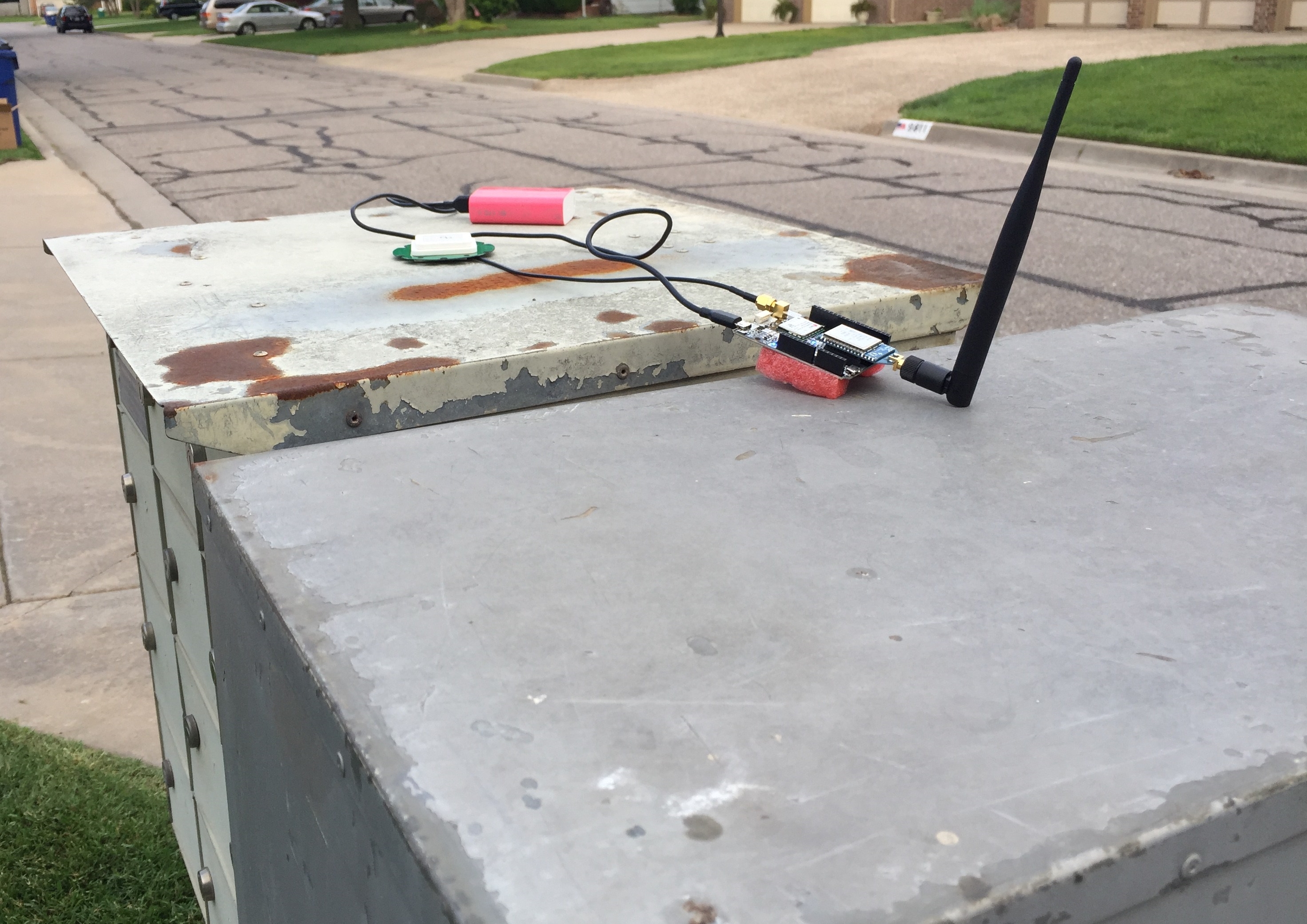
So I’ve spent most of my time testing the wheelchair robot and the RTK GPS system. I have been typically placing the base on my community mailbox because it is geostationary, has a large metallic surface to prevent multipath, and a decent view of the sky.
The base station, located on top of my community mailbox. The green disk is the antenna. Neighbors give me funny looks when they go to get their mail.
Surprisingly, I was able to get several RTK Fixes partially underneath my large maple tree in my front lawn. While in RTK Fixed mode I had the rover running a mission with 10 waypoints in a 3m diameter circle. I cranked down the waypoint radius to 0.3m to try and make sure the robot was accurately traveling to each waypoint.
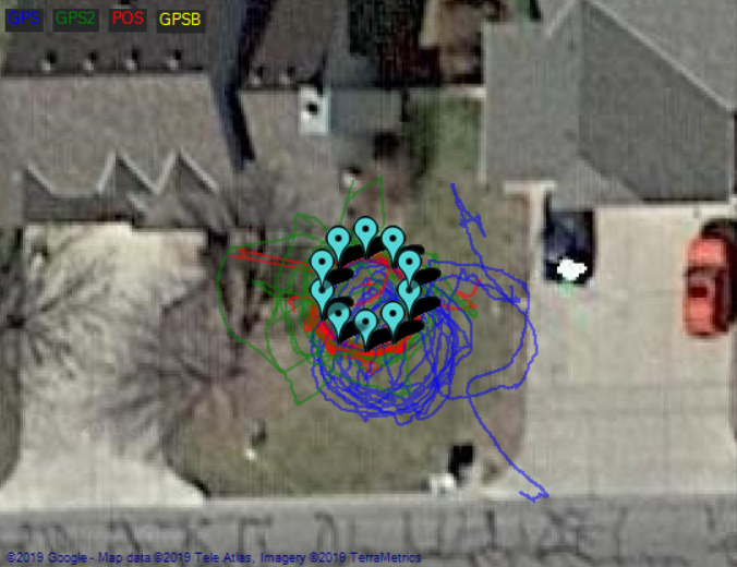
The circular mission in my front lawn. The satellite imagery is from winter time. GPS in blue is the U-Blox Neo-M8N, GPS2 in green is the U-Blox Zed-F9P, and POS in red is the calculated position by the EKF.
The map above shows some calculated positions prior to obtaining the RTK fix and after the RTK fix is lost.
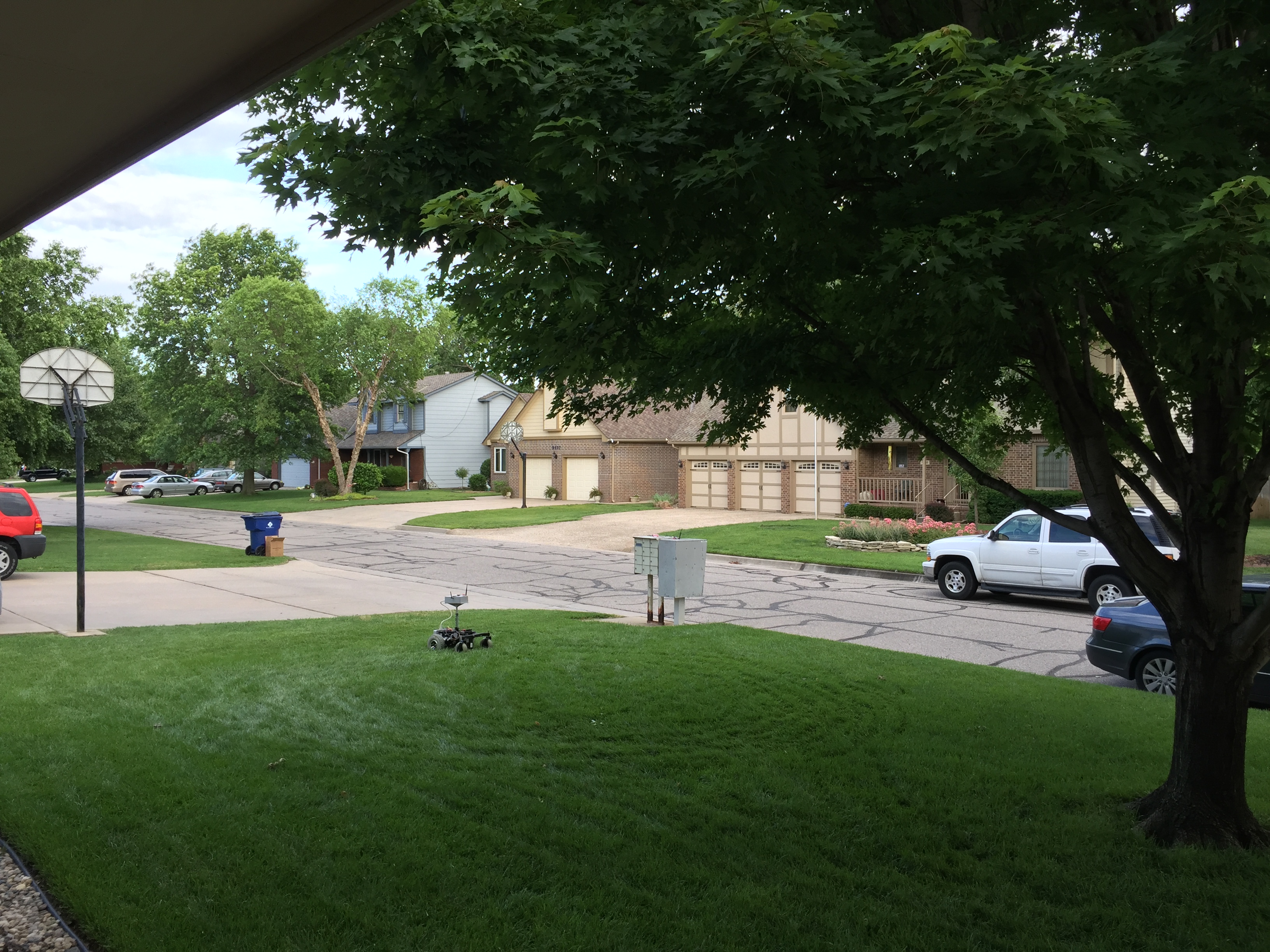
The view from the ground. The mailbox in the picture is where I have the base station sitting.
There is some offset between the satellite imagery and the actual location on the ground, which makes things a little confusing, especially when planning a mission close to many obstacles. I almost ran into my neighbor’s basketball goal after I lost my RTK fix.
To give you a better idea of the quality of the fix, here is the latitude reported by the GPS receivers and the blended location as calculated by the EKF:
The latitude reported by the U-Blox Neo-M8N, U-Blox Zed-F9P, and the EKF position estimate in blue, green, and red, respectively.
The RTK fix in the graph above is first obtained at 18:06:15 and is maintained intermittently until about 18:14:12. The reported HDOP for both GPS receivers was close to 0.7, but despite this, I am impressed that by default, the EKF is giving much more weight to the RTK solution. You can see this in the graph: the red and green lines are much closer than the blue line.
The oscillations in the graph above are from the circular mission I was running. It looks like I had a pretty good RTK fix from about 6:09PM to about 6:13PM. This was about 11 laps about the circle.
Some additional information about the fix status:
The fix status across time. 6 is an RTK Fix, 5 is RTK Float.
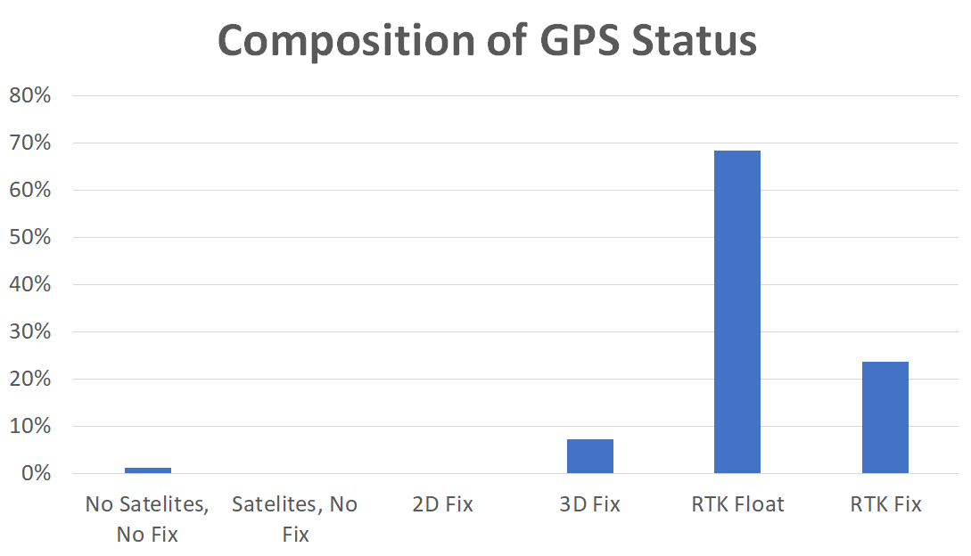
How much time was spent in each fix status.
I don’t want to oversell these results, because they weren’t typical of the entire afternoon. I spent a good chunk of time running the wheelchair robot in Acro mode tuning the throttle and steering parameters, and I wasn’t able to get an RTK fix throughout that time. It’s very much a patience thing.