An Even Better RTK Fix

Several comments on my post about the RTK GNSS results I experienced in the parking lot have made me reconsider how good my RTK fix really was. I was able to get a fix pretty easily, but it was fragile, and would frequently drop back to float without any apparent change in the environment. 

When searching for ways to improve the robustness of the RTK fix, I came across this very comprehensive discussion about u-Blox receiver settings. The consensus I gathered from the discussion was that there are two configuration changes on the ZED-F9P boards that can really improve your RTK fix robustness: tightening up the elevation mask and increasing the signal to noise threshold.

To change these settings, I connected the ZED-F9P module via USB to my computer and then connected to it within the u-Center software. I then went to View > Generation 9 Configuration View. I double clicked on the Advanced Configuration on the left pane to show all the various configuration items.

You can use the CFG-NAVSPG-INFIL_MINELEV configuration item to set the elevation mask. This angle is measured from the horizon upwards. Satellites below this elevation are excluded from the navigation solution. The default is 10°, which I changed to 15°.

You can use the CFG-NAVSPG-INFIL_MINCNO configuration item to set the signal to noise ratio. The default is 6dbHz. I set mine to 35dbHz.

It was kind of a pain to remove the module from the robot, connect it to my laptop, change the settings, and then replace it in the robot, so I didn’t do any A-B testing on these values, although I may in the future. The 15° elevation mask and 35dbHz signal to noise values were recommended from the discussion linked to above.

I did do an A-B test on an aluminum foil ground plane to see how that would improve the fix quality.

IMG_6167
An aluminum foil ground plane underneath the RTK GNSS antenna.

Below is the results with and without the ground plane. Initially I had the robot parked in my driveway under some trees, but after waiting more than 10 minutes for an RTK fix, I decided to drive the robot out in the street where there was a better view of the sky. Shortly thereafter, I got a fix.

no foil ground plane nsats + status
The RTK GNSS performance without a foil ground plane. Left vertical axis is fix status where 6 = RTK fixed, and right vertical axis is the number of satellites seen by the receiver.

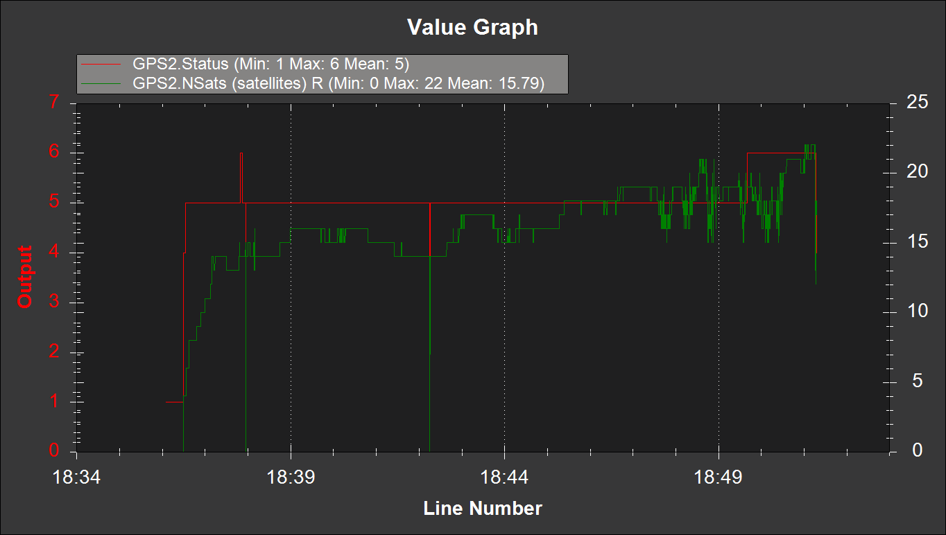
But with the foil ground plane, I was actually able to get a fix in my driveway under the trees. I drove the robot along my street at about 2:30 to see how robust the fix was. Much fewer hiccups, even with a more challenging environment.

With foil ground plane nsats + status
The RTK GNSS receiver performance with a foil ground plane.

I ran the same mission down my street and back with and without the foil ground plane. The ability to keep the RTK fix with the foil was quite surprising. It’s definitely an improvement.

I will take these settings and foil ground plane to the parking lot soon and see how they perform.

The Right Problem

When I mow my lawn, I spend five minutes putting on mowing clothes and walking out to the garage to grab the mower, and this experience has influenced the productivity solution I think the lawn care industry needs. The pain I experience involves pushing the mower. Lawn care companies, on the other hand, experience pain in a whole host of other areas. The two situations are worlds apart, and the comments on my last post made that crystal clear. Thank you to those who shared their thoughts!

As I think about these ideas, I’m starting to realize the problem I’m solving really isn’t the right one. The tag line on this blog is “a project devoted to an autonomous lawn mower.” But the real goal is actually increasing lawn care productivity. An autonomous mower is only a means to accomplish that goal.

Greenzie and Mowbotix haven’t succeeded yet because they haven’t built a system that increases lawn care productivity. While they have successfully removed the operator from the mower, they’re making a mistake by trying to sell it to lawn care companies. Integrating an autonomous lawn mower with the way lawn care companies operate today actually makes them less efficient.

Lawn care companies are just as much about logistics as they are about mowing grass. Successful lawn care companies are able to quickly ferry workers and mowers to multiple job sites throughout the day. But to do this they use expensive tools: a truck and a trailer. And beyond the cost of the truck and trailer, they also waste a lot of time travelling between job sites.

These are major costs that get baked into the price people pay for mowing services. Which is great: it means that there is a lot of waste in the way lawns are currently mowed, and that it’s possible that a new way of mowing lawns can exploit these inefficiencies for profit.

Innovators in the Autonomous Lawn Mower Realm

As I’ve been working on the mower project, I find myself returning to a few blogs and websites to see how other people are trying to automate lawn mowers. It’s fun seeing different solutions to the problem, and I use their successes and failures to spur my own creativity.

This is a list of innovators that I’m aware of in the autonomous lawn mower realm. If you know of some folks that I haven’t found yet, post a comment and I’ll add them to this list!

MowBotix

These guys had automated a fully autonomous riding lawn mower back in 2017, so I think they win the prize for first large scale autonomous lawn mower. They went silent about a year ago and recently posted on their blog that they’re moving toward a more holistic terrestrial software solution that isn’t just for mowers.

Greenzie

Every once in a while I’ll do a Google search for “autonomous lawn mower” to see what I can find. That was how I found the folks out at Greenzie. They appear to be taking the same approach MowBotix did: start with a riding lawn mower and retrofit it with a suite of electronics and sensors. Their solution looks a lot more robust than MowBotix’s, but also quite a bit more expensive. Their Twitter account is a fun time, lots of cool demonstration videos.

Left Hand Robotics

As far as I can tell, the folks over at Left Hand Robotics started out trying to make an automated snow plow. Based in Longmont, Colorado, I’m sure that’s a very welcome solution. It appears they took their snow plow platform and put a mower deck on the front. Voila! Instant mowing platform.

The downside? It appears these bad boys cost an arm and a leg. Or perhaps just a left hand? I’ll show myself the door. This source says their snow plow solution costs $55,000 and has an annual subscription fee of $4,250. However, for that price I’m sure the system works very well. Their videos are quite impressive.

Deep South Robotics

Robo Robby over at Deep South Robotics has a full up riding mower automated with linear actuators to run the steering arms. With his software and hardware chops it appears to be a very robust solution. I admire his willingness to share his methods along with his successes and failures. The comments on his blog are quite informative. Every time he posts, I learn something new.

Evatech

Well, kind of. Evatech makes a series of radio controled lawn mowers, and BitDog from the ardupilot forums took one and added some special sauce to automate it. I admire the simplicity of this solution. It seems to be quite plug and play. But I’m left wondering why Evatech doesn’t take the leap and automate their platform themselves. Their machines are on the pricy side, but being gas powered are probably pretty reliable.

Kenny Trussell

Kenny was the first person I know of (other than possibly the folks at MowBotix) that used an RTK GPS system on a riding lawn mower. He continues to improve his mower, and I look forward to some updates of his progress soon! Kenny shared a very useful waypoint generation program for creating a mower mission in Mission Planner. If I ever get my mower finished, I will likely be trying it.

The Ardupilot Forum

There are quite a few folks on the Ardupilot forum that are working on their own solutions. I won’t post names here, but a cursory search will bring up several of them.

Mean Green Mowers

autonomous_mower_fmt
Mean Green Mower’s autonomous mower. Great minds think alike?

These guys have partnered with a company called Kobi to build an autonomous robot whose anatomy looks surprisingly familiar. I think the solar panel is a bit over the top though. When your deck motors pull multiple kW’s of power, a 200W solar panel isn’t going to be very helpful in my opinion. But it’s great marketing, especially when your company has “green” in the name.

One thing is for sure, it’s an exciting time to be working on autonomous lawn mowers!

Encoder Math

I was able to test the wheel encoders on the wheelchair robot the other night. I had mixed success. The rpm1 and rpm2 status values in mission planner were all over the place. But they were consistently the same magnitude positive or negative:

RPM1 and RPM2
Reported RPM values for the left and right motors.

So something is not right. Talking with the folks on the Ardupilot forum it sounds like I selected an encoder that has too much resolution for the speeds I’m running the motors at.

So to make sure I’ve selected the correct encoders (or to determine which encoders I should have selected) I need to do some math. The encoder I purchased is an E5-900-394-NE-S-H-T-3. It’s rated for 900 counts per revolution of the encoder (CPR).

Maximum Encoder RPM

Encoders have a maximum speed at which they can spin and still accurately measure angular rotation. Per page 4 of the E5 datasheet, an E5 encoder rated for 900CPR can spin at a maximum speed of 20,000RPM.

The encoder is attached to the motor armature shaft, which is in turn connected to a 32:1 gear box. So based on this maximum encoder speed and gear ratio, the fastest corresponding tire rotation speed is:

max tire speed
The maximum rotation speed of the tire on the gear motor for a given maximum encoder rotation speed.

Connected to a small 12V battery, the tire rotation speed was about 60RPM. Doubling that on the wheel chair robot (it has a 24V power supply) is still well below this maximum speed.

So I am confident the encoder can report rotation measurements accurately. Now whether or not the Pixhawk can read them at the speed it reports them is another story altogether…

Frequency of Pulses

How fast is the encoder sending pulses? Let’s say that the tire on the gear motor rotates at 150RPM. Because it’s a quadrature encoder, you get four pulses for every count. The frequency of pulses is then:

pulses at 150rpm
The number of pulses in one second if the tire on the gear motor rotates at 150RPM.

That’s a lot. It’s one every 3.47 microseconds. Can the Pixhawk handle that? I’m not sure.

Resolution

What distance does the robot travel per encoder count? The diameter of the tire is 10in:

travel per count
The distance the tire travels after one encoder count.

That’s a ton of resolution. Way more than we realistically need. Something in the neighborhood of 0.03in/count is more reasonable.

Pull Up Resistor

Another tip I got from the Ardupilot forum was to use two 10kΩ pull up resistors between the A and B signal pins and the Vcc pin on the encoder. I tried that last night without much success. I also tried to pull the A and B signal pins down to ground, but that didn’t work either. I tried it on the left encoder but not the right to see what the difference would be. The numbers were still all over the place, but they were now slightly different. So there’s that.

Going Forward

I am going to purchase an encoder with 32CPR, which results in 1024 counts per tire revolution, and a resolution of 0.031in/count. Hopefully this will be compatible with the Pixhawk. If the 32CPR encoder still doesn’t work, at least I’ll know the issue is something else.

The Magic Number is 31.8

The rotary encoders arrived today. To familiarize myself with them, I decided to use them to try and determine the gear ratio of my wheelchair gearmotors. The idea is that I can rotate the tire a fixed number of times, read the encoder output and then do some math to figure the gear ratio. I’ll need this number for using the wheel encoders with the Ardupilot software.

IMG_4373
The rotary encoder mounted to the wheelchair motor.

Installing this guy was very easy. Peel the cover strip off the adhesive on the back of the encoder and use the conical centering tool to align the base to the shaft. Press it down so it sticks, and then screw everything else into place. Very nice.

The more difficult part is reading the encoder output. To do this I used my old Arduino Uno and did some googling for a sketch that looked close to what I needed (remember I’m a mechanical engineer, not a computer guru). No need to re-invent the wheel, right?

And lo and behold, I found this webpage. And the sketch was pretty much plug and play, short of playing with the baud rates. Not bad for 15 minutes of work!

The encoder I purchased is rated for 900 pulses per revolution. I could have tweaked the sketch so that it measured actual rotations, but I figured I’d just do the math outside of the sketch.

IMG_4374
The setup for measuring the wheelchair gearmotor gear ratio. The encoder and Arduino are measuring input shaft revolutions and I’m measuring tire revolutions with my eyes.

So I taped a pencil to the wheel, hooked it up to a battery and started measuring tire revolutions. After 152 revolutions (measured by aligning the pencil with the motor), the Arduino sketch read 17401196. Dividing that large number by 152 and also by 3600 (it’s a quadrature encoder, so 900 PPR times 4) should give the gear ratio.

The magic number appears to be 31.8. I’m told that gearbox manufacturers like to use strange ratios so that a tooth on one gear doesn’t always contact the same tooth on another gear every revolution. This helps the teeth wear evenly. That’s the only explanation I can think of for this funky number.

I might hook the other encoder up to the output shaft and to get some additional resolution…

Spring is Here!

It’s been a while since I’ve posted, but that doesn’t mean I haven’t been busy. The back yard is starting to really green up and I think the worst of the cold is finally behind us here in Kansas.

IMG_4337
The backyard on this fine spring morning. Winter is finally over!

I purchased a replacement relay board for the one that went bad several of weeks ago. Unfortunately, I didn’t read the fine print and the new relay board requires you to ground the appropriate pin instead of applying 5V to it in order to trigger the relay.

Since I’m now using a high current relay to switch the Sabertooth, I decided to resolder the damaged terminals on the relay board and put it back in the enclosure to switch the high current relay. I’ve taken the wheel chair robot out and tested it, and it is working quite well.

The RTK GPS system is working great, but unfortunately my backyard is still a very challenging environment to work in. Maintaining an RTK fix for 50% of the time is about all I can do. Because of this, I am exploring two different improvements to the wheel chair robot.

Optical Flow

For the uninitiated, optical flow is the concept that modern computer mice use to measure the motion of the mouse. An integrated circuit with a built in “camera” takes rapid (500Hz-ish) pictures. The pictures are very low resolution, 16 bit grayscale or thereabouts, and really small, like 32 pixels square. Using math, the vector difference between each frame is computed, and if you know how far above the surface you are you can then estimate your translation.

The same concept can be applied to our robot wheelchair. Take a camera, point it at the ground, measure how far the camera is above the ground and voilà! With some creative coding, you can estimate your robot’s translation. Optical flow is great because it measures your vehicle’s absolution translation, not some intermediate measure like wheel turns or integrating accelerations to back into your position.

What’s really cool is the Ardupilot code already features optical flow! There’s only one catch… it’s currently only implemented for copter. So for the time being, I’m going to have to either bribe a genius on the internet to port the code to Ardurover, or I’ll have to do it myself. I’ve started playing with the Ardupilot code, but let’s be real. I have no clue what I’m doing.

Wheel Encoders

This is a feature that is already implemented in the Ardurover code. I’m thinking about buying some rotary optical encoders to leverage this feature. For ~$140 I can get two encoders and pretty much plug and play them into my motors.

encoder on motor
The wheel encoders mounted where the brake used to be on the motor. Fits like a mitten!

To properly implement them, I need to figure out the gear ratio on the gear box. I measured it by counting turns of the back shaft on the motor per one wheel rotation and came up with a ratio of  32:1. I thought this was an odd ratio (I was expecting 30:1 or 60:1) so I did some digging and it turns out there’s a little bit more going on in that box than I initially suspected.

To measure the gear ratio, I could just use the encoders and hook them up to an Arduino, measure several wheel rotations and then see how many pulses I get out of the encoder, so I’m not going to bust open the gearbox and start counting teeth. In theory though, this would be the correct way to determine the exact gear ratio.

Some things I’m not sure about:

  1. How much wheel slip is acceptable before the encoders actually start degrading position estimation instead of improving it? Wet grass isn’t nearly as friendly as concrete.
  2. How many pulses per revolution (PPR) do I realistically need? Not much is my guess, but if the Pixhawk can read them, the more the merrier. Where’s the sweet spot?
  3. The wheel encoders help if you can continue to get good absolute positioning information from the RTK GPS. But they’re only as good as your initial position, and you’ll quickly start experiencing drift once you lose your RTK fix. How long can the wheel encoders tide you over between RTK fixes?

For ~$140, I think I’ll take the risk and see how well they work.

u-Blox ZED-F9P

As Roby over at Deep South Robotics can tell you, there is a lot of snake oil being peddled in the RTK GPS space. I’ve been a quiet spectator in this area for as long as I’ve been working on the mower project, and I’ve seen a lot of systems come and go.

Two modules that I had my eye on for a long time were SwiftNav’s Piksi V1 and Emlid’s Reach. Both were L1 only systems. I religiously visited their forums and poured over commenter’s experiences with both modules. In a nutshell, here’s what I learned:

  1. L1 only systems can take a long time to get an RTK fix, and they can lose them in a heartbeat
  2. If you’re in the air with a quadcopter or fixed wing plane, an L1 system generally works well because there is no multipath
  3. If you have any kind of multipath that you are contending with, you are absolutely screwed with an L1 system

On top of that, integrating these systems require that master’s degree in computer engineering I talked about earlier (remember, I am a lowly mechanical engineer, wires aren’t really my thing). Neither system is truly plug and play, from what I can tell. A lot of the integration has to do with injecting GPS corrections through telemetry over MAVLink, as I understand it.

Then last year I discovered that u-Blox was coming out with their own L1 system, the NEO-M8P. I watched a very thorough introduction to the module and was almost going to buy one when I noticed that u-Blox was coming out with a multi-band, multi-constellation RTK GNSS receiver, the ZED-F9P.

I contacted the folks out at u-Blox and they said that an evaluation board would be available in Q1 of 2019, but in my research I stumbled across the folks at Ardusimple. These guys are making a similar evaluation board for the ZED-F9P module that includes a Pixhawk GPS port. Talk about simple.

Is this the holy grail of RTK GNSS? From my experience with this board so far, the answer is yes.

A Simple Test

I conducted a test similar to the one in the video I linked to above. I took reported baseline measurements from u-Blox’s u-Center software, converted the NED components to a net distance and then compared the value with a tape measure.

img_4197
The test setup. The receiver on the left is the base, the on the right near the laptop is the rover. Yes, that is my neighbor’s two story houses in the background.

I intentionally placed the receivers in a really crappy area of my yard to see what these modules are capable of. My neighborhood has lots of two story houses, and many fully grown trees, although they are without leaves this time of year which certainly helps. Here’s a panoramic shot of the backyard, with my house to the right:

img_4193
My backyard. The deck where the test was conducted is on the right.

Bottom line is that this was a pretty challenging multipath environment. I would estimate 50% of the horizon was occluded by my and my neighbor’s house. The remaining areas were pretty well covered up to about 20° if you exclude bare trees. How well did the modules perform?

It’s tough to see in the picture but the NED measures in meters are:

N = -2.1990    E = 0.1063    D = -0.0006

Using the 3D distance formula on these components and converting to inches gives a baseline distance of 86.6759in. You can see in the picture above that the rover antenna is sitting right at 87in. Holy geography Batman indeed!

Some Other Observations

A few other things I noticed in my brief time working with these modules:

  1. The Ardusimple boards have the LED status “backward” from what you’d expect. No corrections means solid blue light, receiving corrections but no fix is blinking blue, and RTK fix is no light. Counter intuitive, but their documentation does mention this.
  2. Just for fun I covered the antenna and waited for the light to turn on, indicating the RTK fix was lost. When I removed my hand, the light would turn back off consistently after less than a second. It appears that if you lose your fix with these modules, you can get it back very quickly, even in a challenging environment.
  3. I kept moving the boards toward the alley between my house and my neighbor’s house, just to see what it would take to force the modules to lose the RTK fix and I was able to get as far as 227in from the base point in the picture above, which was about 3 feet away from my covered patio area before I lost my RTK fix.
  4. Even after I lost the RTK fix, the baseline error was only 12in in 3D float mode. Still really good. Keep in mind during most of this test, I am standing at the laptop taking pictures and fiddling with u-Center. So my body is blocking some signals, too, I’d imagine.

So far these boards are looking awesome! Next step is to hook things up to the Pixhawk.

Lithium Batteries

What would a composite lithium ion battery look like if we were to use one for the mower?

Untitled
What the performance of a hypothetical lithium ion battery could look like if we were to use one.

We need a nominal voltage of 24V, so if you string 7 18650 batteries with a nominal voltage of 3.6V you’d end up with 25.2V, which should work fine.

String 15 sets of those 7 rows of batteries connected in series together and you get a battery with 45Ah of charge. Not too shabby. This would be a 7s15p battery in lithium ion parlance, I think.

Two of those 7s15p batteries would fit in each of our two battery bays. You’d need a total of four to achieve the numbers shown above. They’d fit in our robot something like this:

Lithiums
How the lithium batteries would fit in the battery bays. Very compact. Very expensive.

The weight savings here are significant: 70lb. This is to be expected, but I’m surprised it’s this high. I don’t have a truck to haul this robot around in, so the lighter I can make it, the easier it will be to take it out for field testing. The reduced weight should also decrease the power consumption from the robot’s drive motors, making it more efficient, and possibly more agile.

The cost is still going to be over $1,000 though. Talking with some suppliers, I think the 18650 cells cost a little less than what Amazon will quote you, probably closer to $4.50 per cell. But you still need some fancy charging equipment, and there will be labor and material cost for building up the battery and coming up with a way to secure them in the battery bay.

I may start out using SLA batteries because the monetary risk is pretty low, about $300. They may perform better than I’m expecting. If they don’t, the lithium ion batteries appear to be a good plan B if we need more run time.

Power Consumption

I decided to make the autonomous lawn mower fully electric for one big reason: If a person has to walk out to the mower with a gas can and refill the tank, is it really autonomous?

Ideally, you want the mower to do it’s job without any human intervention. If you have a gas engine, no matter how you cut it fuel has to be delivered to the mower in some fashion. With an electric design, you can have the mower automatically dock with a charging station when the battery gets low. No human required.

So from the get-go I have been trying hard to make the mower electric. I am encouraged by some electric riding mowers out there that use SLA batteries as their power supply. I like SLA batteries because they contain a lot of energy and are fairly cheap. Minimizing battery weight and volume isn’t a huge constraint for this project, thankfully.

Because these electric riding mowers cut grass and carry a ~200lb person on the mower, I have been operating under the assumption that as long as our batteries are larger capacity than those on this riding mower, we should be okay. That Ryobi mower features a battery bank that consists of four 12V, 25Ah SLA batteries.

I am beginning to question that assumption…

Power Consumption

Sizing the batteries ultimately depends on how much power the mower needs. The deck motors take the lion’s share of power consumption. Previously I estimated the mower would require motors that can output at least 5ft-lbf of torque to cut through thick grass based on typical gas engine torque output.

Examining the torque curves for the E30-400 motor I selected for our design shows that at 5ft-lbf or 3.7N-m torque, the motor consumes 1400W of power. If you assume all three motors pull this level of power, the deck motors collectively consume 4200W.

The drive I’m using on the mower design are stolen from the wheel chair. I suspect they are rated for 500W but I am not sure. The gearbox on them ensures they will generally be operating in an efficient area of their torque curves, so I am going to consume both motors consume 250W, and collectively consume 500W between the two motors.

The control electronics are almost negligible compared to the power consumed by the motors, but I will budget 100W for all the other little things on the mower, just to be safe.

That brings the total estimated power the mower needs during operation to 4200W + 500W + 100W = 4800W.

Battery Capacity

The batteries I’ve selected are four 12V, 35Ah SLA batteries. If you assume we intend to discharge these batteries 100% (and that doing so was physically possible), you could obtain (4)(12V)(35Ah) = 1680Wh of energy. If we were to draw 4800W of energy from these batteries, we would drain them in (1680Wh)/(4800W) = 21 minutes. Yikes.

But it gets worse. Because we’re pulling so much power out of these batteries, it looks like you have to discount the total amount of energy you can get out of them. I’m not entirely sure what that calculation looks like, but from the SP12-35 datasheet, it looks like a 1hr discharge rate only allows you to get 21.8Ah of charge out of each battery. That’s only 60% of the 20hr rate of 35Ah. I could be wrong about this interpretation of the datasheet, please correct me if I am mistaken.

Some Thoughts

Do the motors really draw that much power? Holy moly I hope not. At their most efficient, the motors draw 500W of power. Running the calculations above with this number gives you a run time of 48 minutes. Still not great.

The reality is somewhere between those two extremes. Taking the average of the two gives 35 minutes of run time. I was hoping for something more in the neighborhood of 2 or 3 hours. Going up to some 12V, 50Ah batteries could give us some extra oomph, but I don’t think it will be 3 hours of oomph.

Please let me know if these numbers seem way off base, it’s my best swag at them I can come up with. The last thing I want is a mower that can only cut grass for 10 minutes.


Vehicle Kinematics

comparison-10-13-18-e1539411077256.png
Some different mower designs. From left to right, a one, two, and three mower blade design.

Picture yourself at your local grocery store. Our grocery store has two kinds of shopping carts: the big one that I grab for loading up 24 packs of Mountain Dew, and the small one I use when the Missus asks me to get a gallon of milk and some cans of soup. The small cart is half the length of the big one.

Which of these two carts is easier to navigate through the store? Or worded more technically, which one has a smaller turning radius? I think you can see where I’m going with this.

All else being equal, a smaller wheel base and foot print is going to be easier to control using our differential drive system. A longer mower is going to swing through a larger radius, and is going to be more difficult to control and position accurately. For a given amount of drive wheel rotation, you will get more angular travel at the front of the mower with a longer wheel base than a smaller one.

specs
Some high level measures for the three configurations. I didn’t design them in order of number of blades, that’s why the designations don’t match.

It turns out that there are other considerations that impact whether one cutting blade is the best choice for our mower design. A single blade mower allows for the most simple blade drive system. But as you can see from the table above, the single blade design is almost 9in longer than either of the other two designs.

The extra length tradeoff needs to be weighed against the simplicity gained by the cutting blade system. There is also a tradeoff between number of blades and cutting width. By going with a single blade design, you lose at least 5in of cutting width compared to a two or three blade design.

Long story short, of the three designs, the single blade is pretty inefficient by some measures. It is the longest of the three, has the smallest cutting width, and requires the most material to fabricate. If I’m going to be successful with the robot lawn mower build, these are serious considerations that need to be taken into account.