I’ve received a few of the weldments back from the shop. While I wait for them to finish fabricating the mower deck weldment I’ve started to put some components together.
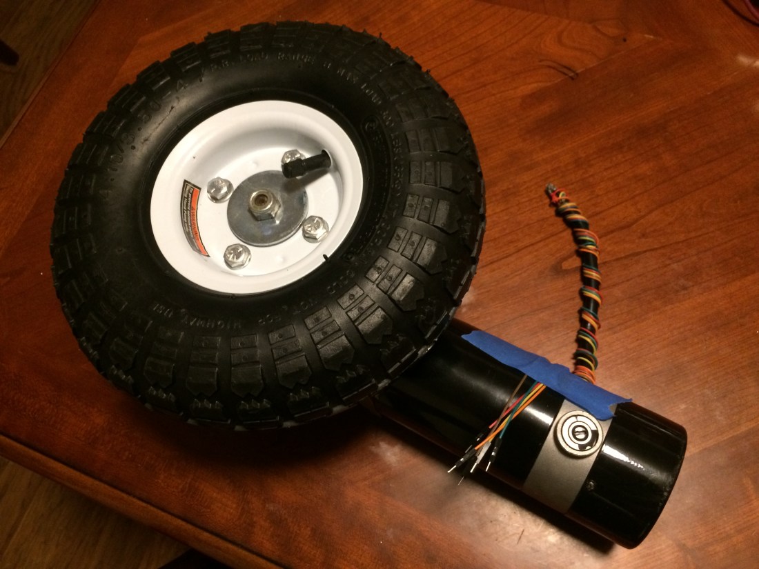
How I initially had the wheel encoders installed. You can see a little rubber grommet in a hole I drilled in the motor dust cover near the bottom of the picture.
Back when I installed the wheel encoders on the wheel chair motors, I stupidly drilled a hole through the dust cover on the back of the motor so I could run data wires to the encoder. In hindsight, I should have run them through the little sleeve that the power and brake wires were routed through.
I had to take the brake off to put the encoder on the motor anyway, so there was a perfect amount of space for the encoder wires once the brake wires were removed from the sleeve.
Because you can’t undrill a hole I purchased a pair of cheap gear motors off eBay for $80. I mostly wanted them for the motor dust cover, but it will be nice to have spare parts on hand in case I need them down the road.
I took the aluminum back piece off the motors and removed the two white wires you see in the picture. The hole you see them sticking through was where I routed the data cables for the encoder.
Pro tip for dealing with these motors: There are two Philips head M5x150 screws holding the aluminum back piece to the mounting plate. These screws have lock washers under them. The screws are ridiculously soft and easy to strip the heads on. If you want to remove them so they’re still reusable, it’s best to use an impact driver. It’s extremely easy to strip them using a screwdriver.
I managed to strip the screws on both motors before I drilled them out and discovered this, so heads up to anyone modifying the motors like I am here. I ordered replacements that were socket head cap screws instead, hoping to avoid this issue in the future.
Once you have the aluminum back piece off, you’ll see wires inside like this:
The inside of the aluminum back piece.
The inside is going to be quite dusty with a lot of little brush particles inside. I blew it out with compressed air after taking this picture.
You can pull the white wires through pretty easily, but I had to bend the black wire terminal so I could get access to the hole to feed the encoder data cables to. I also ended up removing the brushes so I’d have more room to work.
Once you’ve got the white brake wires removed, you can pretty easily push the encoder wires through. The end result looked like this:
How I should have routed the encoder data cables from the start.
One thing I realized doing this is that it would have been pretty easy to drill holes into the aluminum back piece for screwing the encoder base down. I selected an adhesive backed encoder because I didn’t want to mess with it. But going to the trouble to take it apart like this changes that calculus. If I find myself doing this again, I’ll order an encoder that has clearance holes for mounting screws.
The completed motor assembly with the Harbor Freight tire.
After I had everything wired up, I tested the encoder to make sure it was working well. Nothing like having to tear down a motor after it’s already on the robot to fix a loose wire.
I also wanted to make sure that running the data cables next to the power supply cables wouldn’t cause any issues. I didn’t find any during the bench test. Fingers crossed none pop up in the field either.
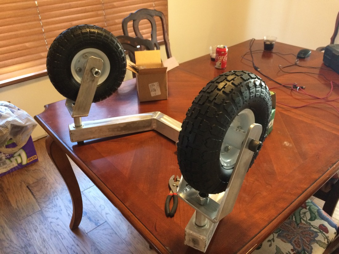
The front caster assembly. A little bigger than I expected!
I used 5/8-11 screws for all the connections in the front caster assembly. I wanted to standardize on one size so I could buy several of one type of lock nut. Unfortunately the width of a 5/8-11 lock nut is 0.9375in and I don’t have a wrench that size. I also don’t have a hex wrench for the socket head cap screws either. The picture above shows everything hand tightened. I’ll have to go pick up the right tools to get this all put together.
I decided to make the autonomous lawn mower fully electric for one big reason: If a person has to walk out to the mower with a gas can and refill the tank, is it really autonomous?
Ideally, you want the mower to do it’s job without any human intervention. If you have a gas engine, no matter how you cut it fuel has to be delivered to the mower in some fashion. With an electric design, you can have the mower automatically dock with a charging station when the battery gets low. No human required.
So from the get-go I have been trying hard to make the mower electric. I am encouraged by some electric riding mowers out there that use SLA batteries as their power supply. I like SLA batteries because they contain a lot of energy and are fairly cheap. Minimizing battery weight and volume isn’t a huge constraint for this project, thankfully.
Because these electric riding mowers cut grass and carry a ~200lb person on the mower, I have been operating under the assumption that as long as our batteries are larger capacity than those on this riding mower, we should be okay. That Ryobi mower features a battery bank that consists of four 12V, 25Ah SLA batteries.
I am beginning to question that assumption…
Power Consumption
Sizing the batteries ultimately depends on how much power the mower needs. The deck motors take the lion’s share of power consumption. Previously I estimated the mower would require motors that can output at least 5ft-lbf of torque to cut through thick grass based on typical gas engine torque output.
Examining the torque curves for the E30-400 motor I selected for our design shows that at 5ft-lbf or 3.7N-m torque, the motor consumes 1400W of power. If you assume all three motors pull this level of power, the deck motors collectively consume 4200W.
The drive I’m using on the mower design are stolen from the wheel chair. I suspect they are rated for 500W but I am not sure. The gearbox on them ensures they will generally be operating in an efficient area of their torque curves, so I am going to consume both motors consume 250W, and collectively consume 500W between the two motors.
The control electronics are almost negligible compared to the power consumed by the motors, but I will budget 100W for all the other little things on the mower, just to be safe.
That brings the total estimated power the mower needs during operation to 4200W + 500W + 100W = 4800W.
Battery Capacity
The batteries I’ve selected are four 12V, 35Ah SLA batteries. If you assume we intend to discharge these batteries 100% (and that doing so was physically possible), you could obtain (4)(12V)(35Ah) = 1680Wh of energy. If we were to draw 4800W of energy from these batteries, we would drain them in (1680Wh)/(4800W) = 21 minutes. Yikes.
But it gets worse. Because we’re pulling so much power out of these batteries, it looks like you have to discount the total amount of energy you can get out of them. I’m not entirely sure what that calculation looks like, but from the SP12-35 datasheet, it looks like a 1hr discharge rate only allows you to get 21.8Ah of charge out of each battery. That’s only 60% of the 20hr rate of 35Ah. I could be wrong about this interpretation of the datasheet, please correct me if I am mistaken.
Some Thoughts
Do the motors really draw that much power? Holy moly I hope not. At their most efficient, the motors draw 500W of power. Running the calculations above with this number gives you a run time of 48 minutes. Still not great.
The reality is somewhere between those two extremes. Taking the average of the two gives 35 minutes of run time. I was hoping for something more in the neighborhood of 2 or 3 hours. Going up to some 12V, 50Ah batteries could give us some extra oomph, but I don’t think it will be 3 hours of oomph.
Please let me know if these numbers seem way off base, it’s my best swag at them I can come up with. The last thing I want is a mower that can only cut grass for 10 minutes.
A simple height adjustment mechanism for the mower deck.
I’m trying really hard not to turn the height adjustment mechanism into a science project. All it needs to do is (1) support the mower deck and (2) allow the height of the deck above the ground to be easily adjusted.
You can find some exciting mechanisms out there to adjust the height of a mower deck. Google Scag Tiger Cat Height Adjustment if you want to see one of the more interesting ones.
A lot of mowers have a mechanism that lets you adjust the mower deck with one single lever. While I like these mechanisms I don’t think they’re necessary for the robot mower. How often do you typically adjust your lawn mower’s height? I do it once a year, if that.
For this project, having to adjust the height in four places versus one is a small price to pay compared to the time it would take to both engineer a mechanism that would work for our robot mower. Not to mention the cost to make it. Springs and linkages get expensive quickly, and the risk it won’t work right goes up fast when you start adding lots of moving parts.
I like simple. I’m not that bright, so I figure if I can envision something working, chances are it will probably work okay in real life. To adjust the height of the deck, pull the quick release pin, rotate the lever to the appropriate height, and put the pin back in. Do that in four places and your done. Simple!
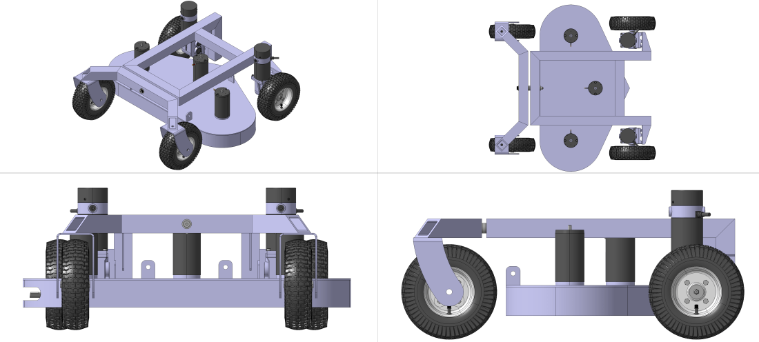
The nice thing about CAD software is you can see how different ideas play out before you spend a fortune to discover they don’t work. The past month or so I’ve been drawing up robot mower designs with little luck. The model above is the only one I feel even moderately good about.
Most of the concepts I’ve put together so far feature a sheet metal chassis shaped around my batteries and motors. The upside with these previous designs is that it allows for the smallest vehicle footprint. The downside is that they involve a lot of welding and waterjet parts, and it’s difficult to come up with a simple mechanism to adjust the deck height because the motors mount directly to the chassis.
This new concept has the mower deck hanging beneath the robot frame. Separating the deck from the robot frame allows both to be simplified greatly. To adjust the deck height I plan on putting a few turnbuckles between the robot frame and the mower deck. An added bonus is that I can disassemble it and throw the robot in the trunk of my small Hyundai sedan for field testing.
One potential downside I anticipate with the design above is that it will be top heavy. The four batteries have to sit on top of the robot frame. We can box them in and secure the to the frame, but I’m not sure what the vehicle center of gravity will look. Guess we’ll have to do some more modeling to find out.
The XLR charger came in the mail today. I was a little worried because it was advertised as 24V output and after I bought it I realized that you really need something like 28V to charge a 24V lead acid battery. The 12V float charger I have is actually 15V at 150mA.
The charger was advertised as being used to charge electric wheelchair batteries though, so I didn’t worry too much. I checked the output voltage and it came it at 27.3V. Not too bad.
The charger label.The actual output is 27.3V.
The connection between the panel mount XLR and the charger was a little disappointing though. It’s tight. Really tight. I’ve been trying to break it in, but I may have to take the panel mount apart and grind down the poka-yoke feature. Just enough to let it slide on though, not enough to remove it completely. It’s there for a reason.
If you think a good design is expensive, you should look at the cost of a bad design.
-Ralf Speth, CEO of Jaguar Land Rover
I know from experience that Mr. Speth is correct. So with a good functional understanding of my electrical components and a wiring diagram in hand, I set out to create a detailed CAD model of the wheelchair.
I do a lot of CAD modeling at my day job, and it’s something I really enjoy. But you don’t have to get anywhere near the level of detail shown below to start seeing real benefit from a CAD model.
CAD modeling is difficult and tedious if you’re doing it right. That’s because you will run into questions like these:
How does that enclosure mount to the chassis?
Where will I position that switch?
Do those components fit in that small area?
Can I route those wires through there?
Is that plate rigid enough to hold that enclosure in place?
In a nutshell, CAD modeling forces you to plan. The more detailed your model, the more detailed your plan. You can choose to do your planning in the garage when you’re scotch taping your Pixhawk and GPS to a chunk of cardboard, or you can do your planning in a CAD program from your air conditioned kitchen while you sip an iced tea. I prefer iced tea.
CAD pro-tip: most stuff is already modeled up somewhere. You just need to know where to look. A good place to start is the manufacturer’s website. Search for the term “CAD model” or “STP file” with the part number after it. Almost everything on McMaster’s website has a CAD model you can download, too. Do some digging. You’ll be surprised what you find!
Reverse Engineering
Before I started drawing up the modifications I was going to make to the wheelchair, I spent a lot of time reverse engineering the existing structure. Would you buy new cabinets for your kitchen remodel before measuring your kitchen? Of course not, and modifying the wheelchair is no different. You’d measure things out to understand your constraints.
It’s important to know what you’re working with so you don’t accidentally put components that interfere with stuff on the wheelchair. But beyond constraints, having a good reverse engineered model also reveals possibilities. Unexpected places to bolt stuff suddenly pop out at you. Places to run wires begin look obvious.
If you don’t have a good set of calipers you need to get some, this will make reverse engineering your existing structure alot easier. The more accurate your CAD model, the more value it will have. Measuring the ID of a hole with a tape measure just doesn’t work that well.
Another cool side effect of reverse engineering something is the learning aspect. Some engineers out at Pride Mobility probably spent a few months hashing this wheelchair design out. I know they put a lot of thought into it. I can learn a thing or two from how it’s built and why it has the parts and features on it that are there.
Hopefully I’ve sold you on the importance of laying things out. Spend several hours thinking about your robot and drawing things out, even if it’s on a dirty paper towel. The alternative is ugly.
A More Robust Robot
How I should have built things the first time around.
No more cardboard. I found these pretty inexpensive enclosures that were the right size for this project. You’ll have to purchase a separate mounting panel if you want something to attach your parts to, which I did. As an added bonus, Polycase provides CAD files of their products on their website.
I mentioned previously that I suspected there was a lot of magnetic interference coming from my motors that was affecting my compass. To try and mitigate that, I decided to segregate all of my power electronics from my control electronics.
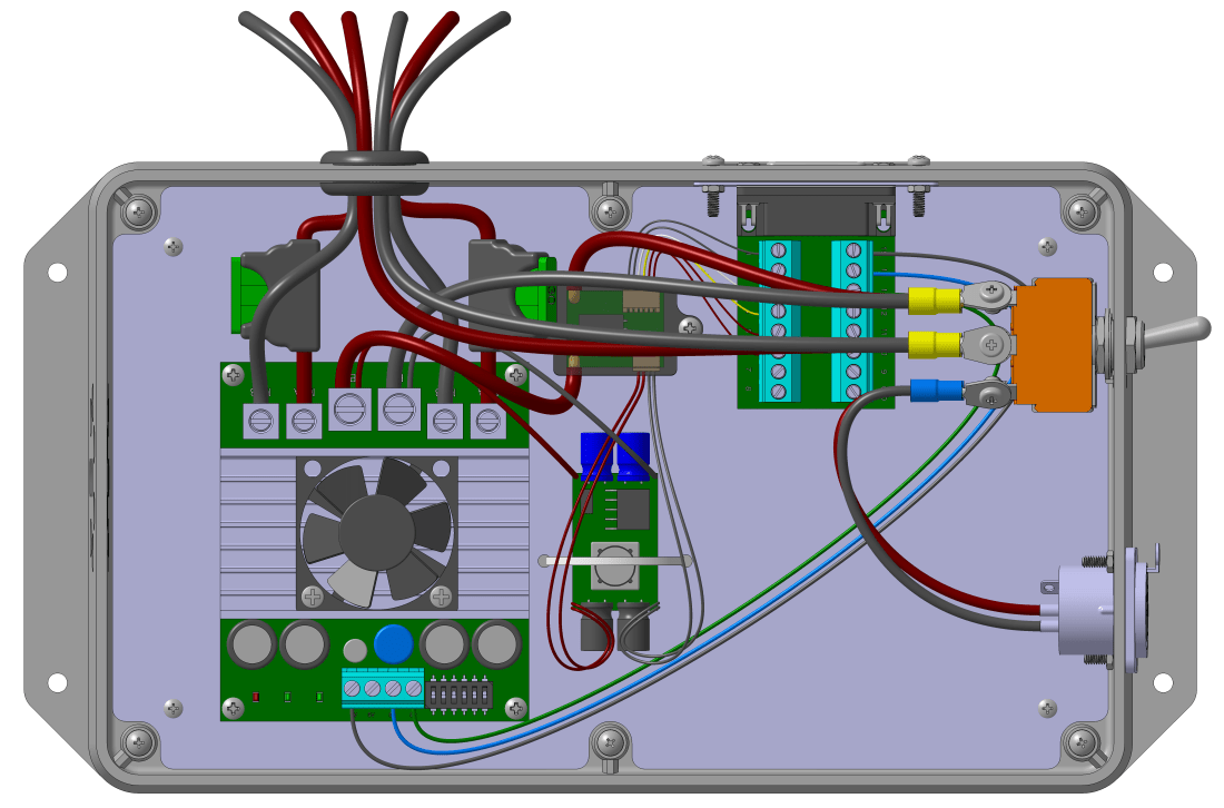
The power electronics enclosure, containing the Sabertooth 2X60, BEC, current sensor, a DB15 breakout board, a three position switch, and panel mount XLR connector for battery charging.
The control enclosure is intentionally oversized for the components it houses. Eventually I may insert some kind of companion computer and RTK GPS unit. Or maybe a camera. Who knows? But at least with extra space, I’ll have options.
The control enclosure containing the Pixhawk, telemetry radio, RC receiver, PPM encoder, and DB15 breakout board.
Connecting the Enclosures
Connecting the two enclosures posed some surprising challenges. Power to the Pixhawk and other control electronics comes from the BEC, which is in the power electronics enclosure. But the control signal for the Sabertooth comes from the Pixhawk. All in all I needed to run 9 wires minimum between the two enclosures.
I spent way too much time researching connectors and wire assemblies, trying to find a cost effective solution. I bought 100ft of phone cable at a garage sale for $2 and initially intended to use that, but how do you connect your wires once they’ve been fed back into your enclosure?
I wanted to avoid crimping my own custom cables because it requires some expensive, specialized tools that I would use once, maybe twice. I also wanted a solution that was plug and play, to allow me to modify things on the go or add additional wires down the road. So soldering was out.
I also had to contend with signal loss through the cables. You can only run a 26 gage wire so far before you start getting noticeable losses. You can double up on small wires to mitigate that effect, but that’s not a proper solution in my opinion. So in summary, my constraints were:
No crimping or soldering
Flexibility for changes in the future
No major signal loss through the cable
One cable between the enclosures
Robust and secure construction
During my research I stumbled upon these D sub connector breakout boards made by Winford Engineering. They even had a CAD model on their website. If you pair these connectors with a cable that is made of something bigger than 26 gage wire you’ve got a pretty good solution, I think. Spend $5 on an old DB15 or DB25 cable at the goodwill, and another $20 for a pair of those D sub connector breakout boards and you’ve satisfied all of those constraints.
The male DB15 breakout board. The jack screws clamp the breakout board to the adapter plate, and the adapter plate screws into the enclosure wall.
There were a few drawbacks to this solution though. I had to make a custom adapter plate to mount the D sub connectors to the enclosure. And the smallest DB15 cable I could find was still 2ft long. Not great, but they don’t make them in 10in lengths off the shelf. And as I mentioned, I’m not too excited to get into the custom cable making business.
The DB15 adapter plate. The center profile is oversized to accommodate both the male and female connectors. The connectors are different sizes, as the metal shield on the male connector slips over the female connector.
I initially intended to make the adapter plate out of aluminum, but looking around it might be just as cheap to 3D print it. The numbers I get back from some quotes I have out will determine what I decide. That interior profile with a +/- 0.020in tolerance is going to be expensive to machine.
Mounting the Enclosures
To mount the power enclosure, I had a small aluminum plate cut. The enclosure is attached to the plate and the plate is attached to the wheelchair base.
I’m trying use something other than steel for material wherever I can to prevent further compass issues. Even absent the compass problems though, steel is difficult to cut through. Unless the rigidity is required it’s probably worth it to use aluminum if you can.
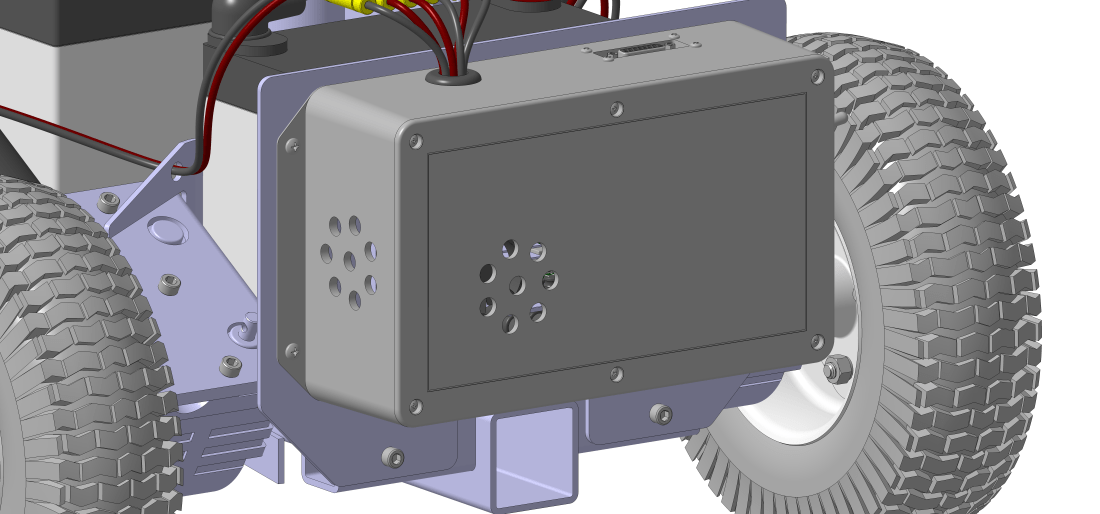
The Sabertooth 2X60 comes with a cooling fan and a nice heat sink. I’ve set up the power enclosure to take advantage of this feature by drilling holes in the enclosure to allow the fan to pull air through it. I also selected the grey colored enclosure instead of the black to try and keep heat retention to a minimum. If you’ve ever owned a black car in the summer time, you’ll know why.
The power enclosure mounted to the robot chassis. The Polycase enclosure comes with two flanges on opposite sides of the box with pre-drilled holes in them for easy installation.
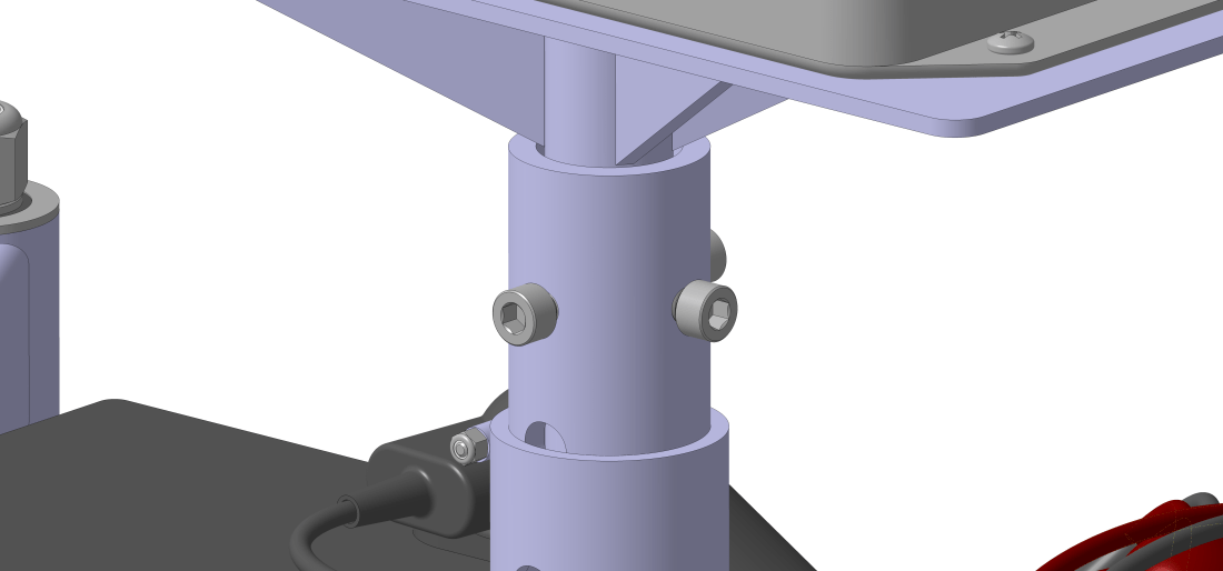
To mount the control enclosure, I made a small pedestal weldment that functions like the seat did before I removed it. This allows me to adjust the height of the enclosure if I need to move it further away from the motors. The enclosure bolts to the weldment the same way the power enclosure does.
The pedestal weldment dummies the function of the seat that was removed.
Connecting the Motors and Batteries
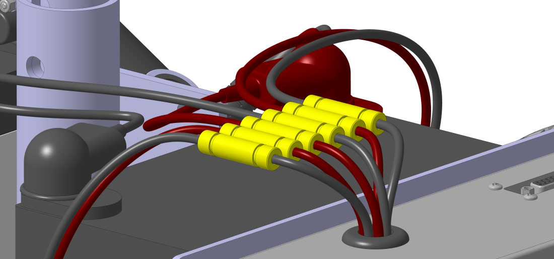
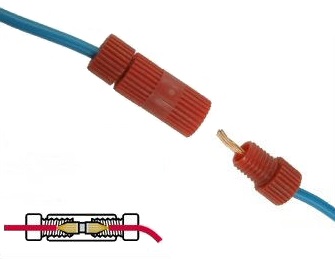
To connect the batteries and motors to the power enclosure, I found these interesting connectors called Posi-Locks. They allow you to both electrically and mechanically connect your wires. Strip the wires, cram them, and cinch them down. They aren’t cheap, but they are reusable.
We’ll see how well they work once I start putting things together. I’m using six 10 gage Posi-Locks for connecting the two motors and B+ and B- battery terminals to the Sabertooth 2X60.
Six 10 gage Posi-Lock connectors between the motors, batteries, and Sabertooth.
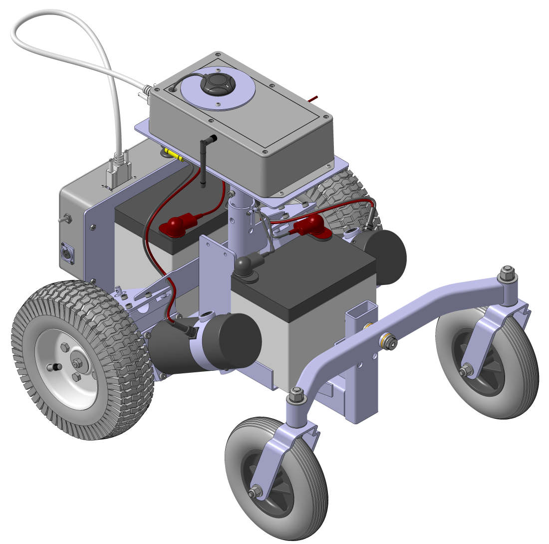
Someday I hope to actually build a robot lawn mower. I’ve tried to design everything here in a modular fashion so I can take this equipment over to the new robot without too much hassle when that day comes.
I previously discussed a lot of issues I experienced with my first robot build that stemmed from a lack of planning. To avoid those pitfalls this time around, I decided that a good place to restart things would be a detailed wiring diagram for the robot.
The wiring diagram. Some familiar components, and some new ones, too.
Sabertooth Protection
Between 2014 and several months ago, I managed to fry the Sabertooth 2X32. I’m not entirely sure how it happened, but the excellent support folks at Dimension Engineering informed me that moving the robot manually can generate enough back current to fry it.
On my previous build I had a switch between one of the positive battery terminals and the Sabertooth B+ contact. The Sabertooth is a regenerative motor controller, meaning any current that enters from the motor leads get fed back into the batteries as I understand it.
Well when that switch is off, current generated by the motors has nowhere to go. Wheeling the robot by hand into the garage generates current (it’s basically a DC generator at that point) and that could have created enough current to blow the Sabertooth I guess.
Alternatively, the geared motors on the robot have a lever that can be used to put the gearbox in “neutral” so that it’s easier to push and so that wheel rotation doesn’t rotate the armature of the motor. If I were smart I would have just flipped the lever.
Dimension Engineering kindly offered to replace my blown Sabertooth 2X32, but I decided to upgrade to the Sabertooth 2X60 instead. For an extra $65 you get a cooling fan (more on that later) and twice the current carrying capacity. Definitely overkill, but one the things I learned on my previous build was to not skimp on quality and robustness.
Notice the two 30A fuses on the M1A and M2A motor leads. If you do get large back current, the fuses should blow before you damage the Sabertooth motor controller. Spending $5 is cheap insurance to protect a $200 part.
Mauch BEC and Current Sensor
Because the Sabertooth can’t output enough current at 5V to fully power the Pixhawk and it’s accessories, I had to find an alternative way to power them. However, because my power supply is two 12V 35AH SLA batteries, I was hesitant to use the stock BEC that comes with the Pixhawk. And in any case, I couldn’t use it to control my motors with, so I thought it would be worth it to find an alternative solution.
That’s when I found Christian Mauch’s line of BECs and current sensors. The wiring for these guys is a little weird, at least to me, but it makes sense once you examine it.
The BEC is connected to the 24V battery supply, but after the current sensor.
The BEC steps down the 24V supply to 5.30 +/- 0.05V at 3A and feeds itinto the current sensor.
The current sensor has a 10 gage wire that sits between the positive terminal of the 24V battery supply and everything else, so it can measure current consumption.
The current sensor then has a 6 wire output that is fed straight into the power port on the Pixhawk.
Got all of that? Here’s the diagram from Christian’s website.
How to wire an HS-200-HV sensor with a 4-14S BEC. Confused yet?
That 5.30 +/- 0.05V is written intentionally. The Pixhawk decides which power supply to use by selecting the supply with the highest voltage. If the servo rail provided, say, 5.2V and the power port on the Pixhawk was supplied with 4.9V, the Pixhawk would use the supply on the servo rail. Christian designed his BEC to output on the high side to make sure the Pixhawk selected his BEC with a clean output for power.
According to the documentation, the HS-200-HV is capable of measuring up to 200A of current. Yep, that’s 200A. And you thought the Sabertooth 2X60 was overkill.
The reason for this choice isn’t completely unfounded. Down the road I may want to have an electric motor for the cutting blade on the mower. I’m not sure how much current that will draw, but it won’t be chump change, I imagine. Hopefully this will provide flexibility in the future.
New Three Position Switch
To charge the SLA batteries on my first setup, I had to remove the two terminal lug screws and attach a 12V trickle charger to the battery. I had to do this twice, once for each battery. Kind of tedious.
On this new configuration, I intend to have a three position switch: one position for on, a neutral position where nothing is connected to the battery, and a charge position, where the batteries will be connected to an XLR port for a 24V XLR charger.
The idea is that you flip the switch up for operating the robot, and down for charging the batteries. For storage you have the neutral middle position so that the charging port isn’t energized by the batteries.
Hopefully these new features will correct some of the problems I experienced on my first build. This wiring diagram will also prove invaluable for the next step of planning.
I learn best through experience. I learn the most through bad experiences. The picture above was a bad experience. Fortunately though, I did learn a lot.
Shortly after I got the electric wheelchair home I took the seat off, removed the plastic cover from the base, and started slapping on my hastily purchased parts.
In my defense, I hadput some thought into what you see above, just not very much thought. And because I’m a tightwad and unwilling to shell out $200 for some connectors, boxes, and other small but very important accessories, I ended up with this hairball.
This post is a list of things I learned the hard way. Hopefully you can learn from my mistakes.
Secure Your Equipment
You’re seeing that right: scotch tape is what secures the Pixhawk and GPS to that platform. Wondering why you’re getting “Bad AHRS” readings in Mission Planner? The fact that your GPS and compass unit can wiggle +/-5° might have something to do with it. Especially if it’s taped to some cardboard that is then zip tied to your robot.
Even if the Pixhawk and GPS/compass unit had been adequately secured on my first iteration of this robot, a lot of other critical components should have also been more secure. Nothing holds the Sabertooth in place except for the 10 gage wire tied to the batteries. Nothing holds the RC receiver in place except the servo cable.
If you want a robust robot, then you need to secure everything. If it is loose, it will fall off your robot and get damaged. Related to securing your equipment…
Vibration Is No Joke
Vibration? That’s something the copter guys have to worry about, not us rover guys.
-Me, 2014
Boy was I wrong. It’s tough to see in that picture, but the cardboard is zip tied to a piece of .030 thick aluminum plate. That plate is bolted to a floor mount pipe flange. The pipe flange has a plastic pipe threaded into it that is then crammed into the seat pipe on the wheelchair base.
I don’t think I could have created more vibration problems if I had tried. What I made was basically a giant diving board to mount the Pixhawk to. You could watch the thing bounce up and down every time I started and stopped when driving in manual mode. I’m sure this contributed to the “Bad AHRS” I was getting in Mission Planner. Another reason to secure your equipment.
Wire Management Matters
When your robot is running over the loose wires hanging off the chassis, you have a problem. Wire runs should be as short as possible and zip tied to your frame. When I had to get my multimeter out to test continuity across wire runs that are electrical taped together, I should have stepped back and said “maybe there’s a better way to do this.”
Related to secure your equipment: wires conduct current, not mechanical force. Yes, I knew this before I slapped this monstrosity together, but this experience gave me first hand experience when a servo cable between the Pixhawk and Sabertooth came uncrimped because the robot ran over a wire tied into the Sabertooth.
Be smart with your wires. Even wire nuts are better than what I’ve done here. Rovers are nice because unlike the guys running RC planes or copters, weight isn’t an issue. But it’s no excuse to get sloppy.
An On-Off Switch is Mandatory
Would you turn on your kitchen light by reaching into an exposed outlet box on your wall so you can bend a wire to contact a terminal? Of course not, and just writing that sounds ridiculous.
But that’s how I powered on the robot, by taking a wire and cramming it into one of the battery lugs. It sparked something nasty every time I did it, and always created a nice little smell afterwards. But more importantly, that was pretty dangerous.
One nice improvement you can’t see here is a switch I jury rigged together after I got tired of the inevitable zap that happened when I connected the wire to the battery terminal. I had an old light switch lying around, so I wired it in by clamping the wire under the switch terminals. Did I secure it to the frame? Of course not.
Power Supply
The Pixhawk needs a nice, clean 5V supply. One of my favorite features of the Sabertooth motor controller is the 5V, 1A BEC output. Unfortunately, 1A really isn’t enough to power both the Pixhawk and any useful peripheral devices, like the GPS and especially the telemetry radio.
The 0V was wired into the − rail and the 5V was wired into the + rail of the Pixhawk. Using this configuration, I experienced regular brownouts. I’m not sure how much current my radio, GPS receiver, and PPM encoder were drawing, but it was enough to cause the Pixhawk to reset not infrequently.
You really need a good BEC that can output a few amps of current to make sure the Pixhawk is well supplied. I skimped by thinking the Sabertooth BEC allowed me to not purchase a good BEC.
Another downside, albeit a small one, was that without a good BEC there’s no way to measure current consumption or voltage drop across the batteries. With two 12V, 35AH SLA batteries though it’s really not a big deal, but it would be nice to get some information about battery state.
DC Motors and Magnetic Flux
Your compass is going to have a bad time.
Brushed DC motors create a lot of magnetic interference. I would liken it to the movie Twister, except with magnetic flux. Your compass is the cow getting sucked into it. This has big implications for your compass reading and ultimately your heading.
When I did try to run the robot in Auto mode, it would weave left and right really bad if I tweaked the skid steer parameters just right, but mostly it would just run in circles, sometimes switching rotation direction. Toiletbowling is the technical term, I think.
I suspect this was because my compass was getting swamped by all of the flux created by the motors. The long cables carrying several amps probably didn’t help either. The ferrous pipe flange could have contributed. But because of all of the other jacked up stuff I mentioned above, I never did figure out the root cause. It was probably a combination of things.
Calibration could also have been an issue. This robot weighed 80+lb, and to rotate it about all axes for calibration was pretty much impossible, especially with the way my equipment was secured. So I was basically rolling with a half-baked compass calibration. So there’s that, too.
The Moral of the Story
I hope that wasn’t too depressing. There is, however, a moral to this story.
Robustness is important. You can’t trouble shoot a “Bad AHRS” error if the Pixhawk is bouncing all over the place. You can’t tune your skid steer parameters if you are experiencing brownouts every 5 minutes. You can’t calibrate your compass if nothing is mounted to your frame. Murphy’s law applies: if it can fail, it is going to. Spend the time and money to do it right. It’s not worth it to do it any other way.
Planning is important. If I had spent even 5 hours laying stuff out and making a wiring diagram, I would have been light years ahead. Where I work we have a saying, “an hour of design saves an hour of rework in the shop”. Basically, you save time and money by planning things out. It’s true where I work, and it’s true with robot building, too.
Go slow and pace yourself. It’s important to do things deliberately and methodically. I was basically just slapping things together trying to get it to work. Sometimes you will get lucky and things will work perfectly. But mostly, you’ll just end up discouraged about the lack of progress. Start with small bits and get them working, and working robustly. Then move on to combining the small bits into larger ones. Rome wasn’t built in a day. A good robot isn’t, either.
Unfortunately, this experience was so discouraging that I stopped working on the mower project altogether for a few years. The wheelchair sat in the garage collecting dust. But it was always in the back of my mind. I cleaned out the garage several months ago and decided it was time to give the mower project another try, but this time with a more deliberate approach. Next time I’ll give some detail about what I’m doing differently this go around.


 To connect the batteries and motors to the power enclosure, I found these interesting connectors called