Vibration Issues (Continued)

The vibration in my mower deck is caused by unbalanced mower blades. The distance between the mower blade’s center of mass and the rotation axis of the motor shaft is often referred to as eccentricity, and this eccentricity results in a centrifugal force as the mower blade’s center of mass is swung around the axis of rotation.

A cheap prop balancer from Amazon with a 0.5in diameter keyed shaft from McMaster Carr. The two head press fit bushings ensures the keyway doesn’t interfere with the shaft’s rotation.

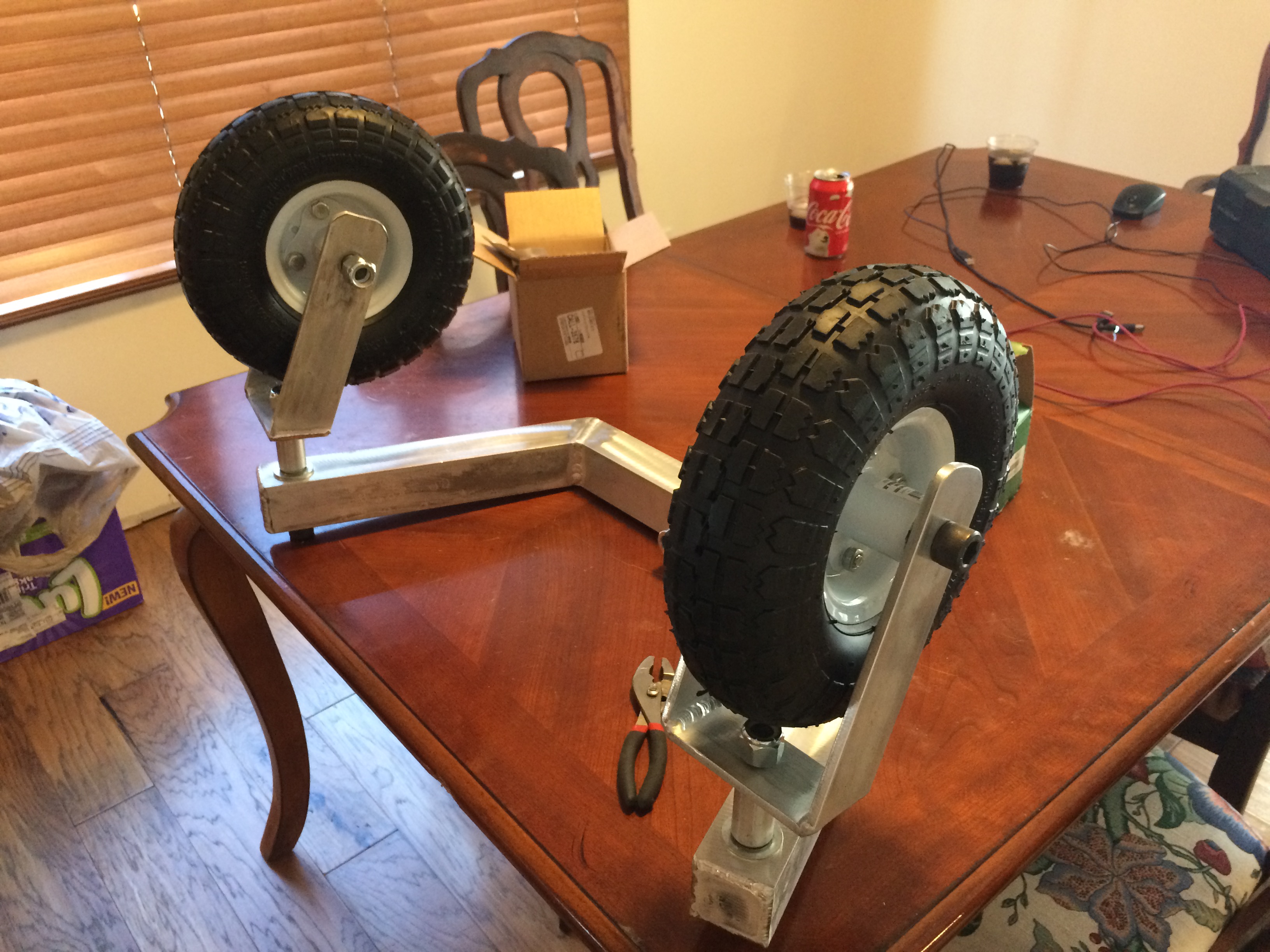
At high rotation speeds, even a small amount of eccentricity can result in a big centrifugal force. To see how far out of balance my mower blades were, I purchased a small RC plane prop balancer off the internet. With a few pieces of hardware from McMaster Carr I was able to get it to work with my mower blades.

One side of the blade was heavy, so I started putting scotch tape on the opposite side to see how much mass it would take to balance the blade. It soon became apparent I was going to need more mass than a few strips of tape, so I stuck a few #8-32 hex nuts on there. Once I got it pretty well balanced, I removed the tape and hex nuts and weighed them.

It took almost 3 grams of mass to balance one of my mower blades.

Because the mass of the blade assembly is not coincident with the rotation axis of the prop balancer, there exists a moment about the rotation axis when the center of mass is not directly below it.

By putting tape and hex nuts on the opposite end of the blade, we created an additional balancing moment. The sum of these two moments must be zero for a balanced blade at equilibrium.

We can measure the mass of the blade, which is 798.1g. We also know the mass of the balance weight, 2.8g. And we know the position of the balance weight: it’s half the length of the blade, 6in.

Using this information, we can solve for the eccentricity:

Calculations for determining the mower blade’s eccentricity, or the distance away from the rotation axis the mower blade’s center of mass lies.

And the resulting centrifugal force is:

The resulting centrifugal force if a mass of 798.1g is 0.021in away from the center of rotation at 4800RPM. I find some calculations are easier to do in SI units, making the conversion back to imperial units at the end.

To be fair, I didn’t get my motors up to 4800RPM. But at speeds near the natural frequency of a structure you get a lot of force magnification, so it’s entirely possible the mower deck was experiencing a force at least that large or larger.

I know what you’re thinking: that’s a lot of words to say “balance the blades, dummy.” But there’s a few reasons this exercise is valuable.

Firstly, it gives me a rough idea of how much material needs to be removed from the mower blade. It needs to be 2.8g lighter on the side opposite where we placed the balance mass. The volume of material that needs removed is:

The volume of material that needs to be removed from this specific mower blade assembly to align the center of mass with the rotation axis.

If the blade is 0.203in thick and about 2in wide, that means we need to grind the end of the blade down by about:

How much material that needs to be ground off the heavy end of the mower blade to achieve balance.

That estimation will hopefully save me a few trips between the blade balancer and the grinder.

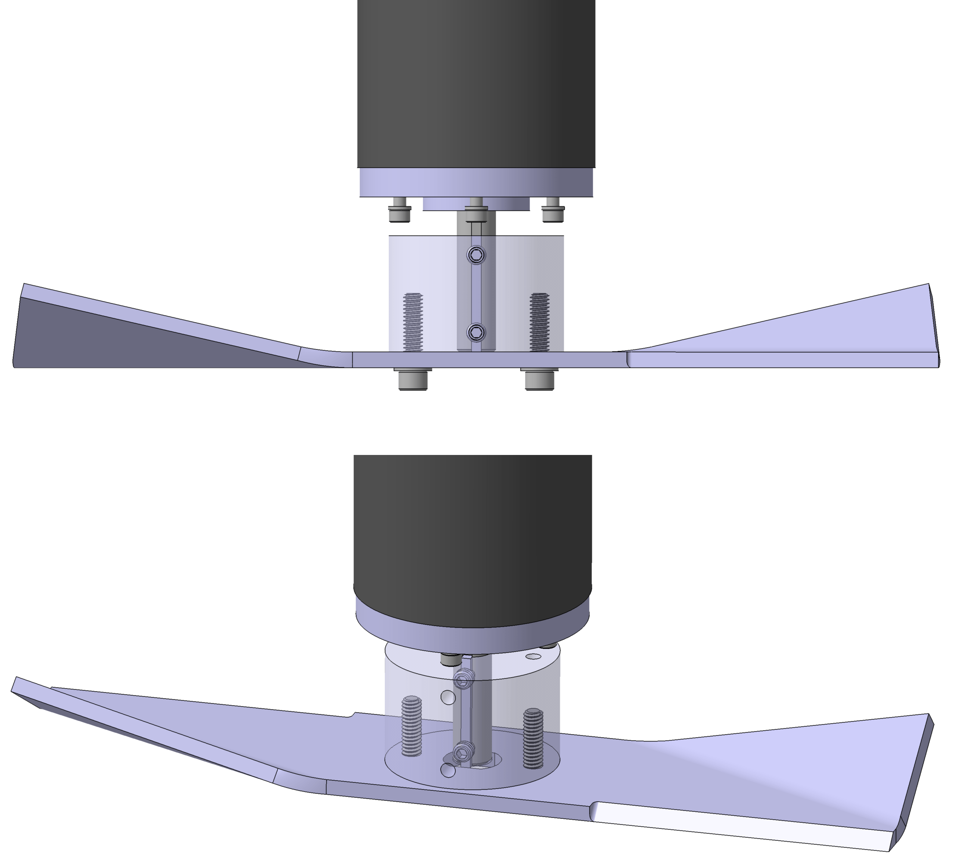
Secondly, these calculations shed some light on how significant the imbalance is between the various blade assembly components. It’s not just the mower blade that’s unbalanced: the adapter, screws and even the motor shaft (it’s keyed on one side, after all) also contribute to the unbalance.

However, their combined mass is smaller than the blade’s mass, and their locations from the axis of rotation are also relatively small. For example, you’d have to add nine 1/4 washers to one of the mounting bolts on the blade assembly to offset the unbalance that exists in the blade:

The number of 1/4 washers you’d have to add to one of the mounting bolts to offset the imbalance inherent in the mower blade.

That stack of washers would be almost 5/8 of an inch tall and weigh 20.7g. So the lowest hanging fruit in our attempt to balance the blade assembly is going to be working on getting the blades themselves better balanced.1

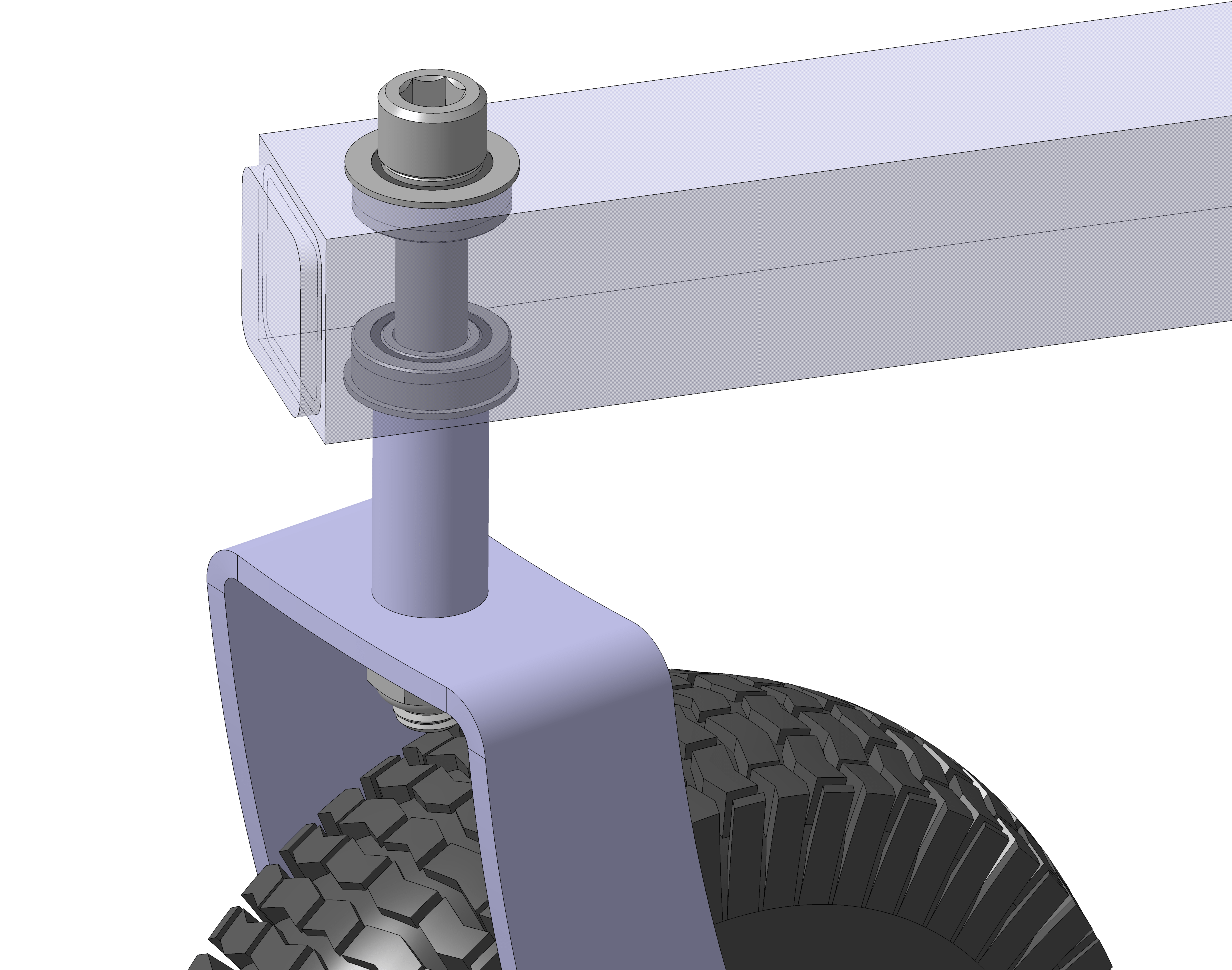
And lastly, these calculations reveal a major flaw with my mower blade assembly design: nothing holds the blade fixed relative to the adapter. The screws are inserted through clearance holes in the blade, and if you loosen them, you can wiggle the blade around relative to the adapter by about 1/16 of an inch.

The bottom of the mower blade assembly. The two screws are the only thing that sets the position of the blade relative to the shaft adapter.

If 0.021in eccentricity already exists in the mower blade, and that creates enough vibration to peel open an eyebolt on my mower deck mounts at resonance, then any slippage of the blade during operation will easily re-introduce that vibration.

It might be worthwhile to redesign the mower blade adapter to locate off the center hole in the blade to prevent this from happening. And to also redesign how the mower deck connects to the robot chassis. But for now we’ll focus on balancing the blades and see what that does for us.

  1. Adding washers like this would likely change the orientation of the inertial axes and introduce couple unbalance. I’m unsure how significant this couple unbalance would be. While one or two washer shims might work for fine tuning the balance, attempting to eliminate the unbalance like this may create a situation where the blade is balanced statically but still vibrates when rotating.

Wiring Improvements

I’ve spent most of this winter re-wiring the robot mower. In hindsight, I should have spent a lot more time planning the wire runs. I made a lot of design choices about how the chassis should look and where enclosures should be located that are inappropriate given my more complete understanding of how the wires need to be connected between components.

At some point you have to build something that’s not perfect and work through the bugs later. It’s against my nature to operate that way, but if I hadn’t started building the robot mower in reality at some point, it would still be a picture in my CAD program.

In the rest of this post, I’ll describe some wiring related improvements I’ve been making to the robot mower.

The original power enclosure. The phrase “rat’s nest” comes to mind.

The picture above is how the power enclosure used to look. It used to contain the Sabertooth 2X60, the voltage/current sensor, the BEC, a positive and negative terminal stud, a small 5V relay board to trigger two larger 50A relays, a power switch and an XLR charging port. It was a mess, to say the least.

The reorganized power enclosure. No relays or terminal studs, just two motor controllers and a BEC.

The reorganized enclosure contains the Sabertooth 2X60, the BEC, power switch, XLR charger port, and a motor controller for the deck motors exclusively.

The reason I tried to pack so many components into the power enclosure was so I didn’t have to put anything other than wires in the battery bay. It is a battery bay, after all. I was hoping to make an entirely modular power enclosure I could build up separately from the robot and then basically bolt on.

While that’s nice in the CAD software, in reality it didn’t work. If I’d selected a larger enclosure it might have been possible. But an unintended side effect of putting everything in one enclosure is that you have to run 24V and ground into the enclosure, but you then turn right around and run a ton of wires right back out of the enclosure.

As I have learned, relays are not a great way to control motors, especially if they’re using a lot of power. And on top of that, those “200A” relays were kind of a scam. They terminals are only rated for 50A, and I’m pretty sure I managed to fry one out in the field. I decided to replace them with a single channel motor controller that can supply up to 200A of current.

The nice thing about having a motor controller driving the deck motors is that I can dial back the blade speed if the mower is cutting the grass just fine. There’s no sense in running at 4800RPM when 3600RPM will do the job. I’m hoping this will allow the robot mower to run for a longer period of time.

A fuse block for the mower deck motors.

I was using wire nuts to connect all of the deck motor wires together originally. I wanted to make things a little more professional than that, so I decided to replace the wire nuts with a fuse block.

In theory, the deck motors should only use about ~30A each at steady state, and with the new motor controller, I think I can spool them up slow enough to where a fuse doesn’t blow. We’ll see how good this assumption is soon.

One thing I like about the fuse block is it allows me to easily disconnect power from the deck motors: just pull the fuses. This makes safe troubleshooting easier. The fuses will also provide a layer of protection for the motor controller. But at the same time, a blown fuse creates exactly the situation that caused my wire failure. I intend to also have a Zener diode between the supply terminal and ground to hopefully protect against this situation, too.

Components relocate into the battery bay. From left to right, there’s an RC controlled relay board, a solenoid, the voltage/current sensor, and a master fuse block.

All of the power in the robot now runs through a MEGA fuse, and from there it runs through the voltage/current sensor. After that, it runs through a solenoid, which supplies power to the drive and deck motor controllers. The solenoid can only be powered if the E-stop switch and RC relay board are in safe states.

I also put rubber boots on every exposed terminal, including the batteries. They look a little ridiculous on that solenoid, but they are adequately insulated.

The RC controlled relay board.

The RC relay board is controlled by a switch on the RC transmitter. If the RC relay board doesn’t detect a valid RC signal, it will open the relay. This allows me to have a remote E-stop switch.

One thing I don’t like about this RC relay board: when you power it on, it automatically closes for a second, then goes open. That’s a really crappy design, in my opinion. But without the Pixhawk armed it’s kind of a moot point.

A proper ground plane for the GNSS antennas. The foil to the left was what was underneath the RTK GNSS receiver previously.

I also finally got around to putting a proper ground plane under my GNSS antennas. We’ll see how much this improves performance.

I hope to have these wiring improvements wrapped up soon. The grass is green and growing out here in Kansas!

Mower Blades: More Complex Than You’d Think

ego-lawn-mower-blades-ab2000-64_1000
A typical mower blade.

While designing the robot mower, I spent a lot of time working on the chassis, electronics enclosures, and wire routes. I tried hard to select components I could easily acquire at a reasonable cost, and that effort paid big dividends when I went to get everything built.

Unfortunately, I didn’t spend nearly as much effort on how the mower blades would attach to my motors, or even what the mower blades would look like. I assumed I could easily find any mower blade size I would need, or that making my own custom blades wouldn’t be difficult.

Now that the blades are the only thing missing on the robot mower, I’m realizing how mistaken that assumption is. I designed the mower deck for three 12in long blades, thinking that surely such a size exists. But most blades are generally in the neighborhood of 20in long.

Small gasoline powered mower engines operate at speeds in the range of 2,500RPM to 3,000RPM, and to achieve an appropriate blade tip speed slightly less than 19,000ft/min, the math forces you to use a blade that is between 19in to 22in long. Blade sizes outside this range aren’t common.

Initially I decided this wasn’t an issue: I’ll just make my own blade. It’s just bar stock with two sharp edges, right? Well, kind of. There’s a fair amount of metallurgical considerations that go into mower blade fabrication. On the one hand, you want a soft, ductile blade that doesn’t shatter when it hits a rock or tree stump. But on the other, you want the blade to be able to keep a sharp edge for a long time, which means making the blade, at least near the sharp edge, more brittle.

Cutting grass creates an inherently moist environment under the deck, so mower blades are usually painted or feature some kind of corrosion resistance. And on top of all this, a good blade will have a small bend opposite the cutting edge to create a little wing so that the grass clippings can be pulled upward resulting in a nice, even height cut.

The more you learn about mower blades the more you start to realize that buying one is really the way to go. In your research you’ll come across horror stories of guys who made their own mower blades and either welded them poorly or jury rigged them to work and then got hurt or even killed by the shrapnel from a blade shattering. Just this video alone should give you pause: there’s a lot of energy under a mower deck.

So off I went to find a 12in long mower blade. The closest I could find was one that was 12.125in long, which leaves 0.375in between the blade tips when they rotate past each other instead of the 0.625in I had designed for. We’re about to find out how accurately the mower deck weldment was made. I really hope I don’t have to grind the ends of the blades down because they crash into each other.

Finding a blade is only half the battle. How do you attach it to the 0.5in diameter keyed shaft on the E30-400 motor? The crankshaft on most push mowers I’ve seen has a threaded hole in the shaft for bolting the blade on. The E30-400 has nothing of the sort.

Could you drill and tap a hole in the end of the shaft? Possibly. But a #10-24 threaded hole is about the biggest you could drill and tap, and that only gives you 0.083in of edge margin from the major diameter of the threads to the keyed portion of the shaft. Too close for comfort in my mind.

The first solution that I came up with was to take a piece of 1.5in long, 2in diameter round stock, bore a 0.5in hole in it, key the hole, and then drill and tap holes for mounting the blade and some set screw holes to clamp the key up against the shaft. But in this scenario, the set screws are the only thing that holds the blade on the shaft. Better than nothing, but not by much.

combined
My first idea for a mower adapter: a machined piece of round stock. Expensive and heavy, not what you want in a blade adapter.


I got a few quotes on three of these parts and the keyway really kills you on cost. I got several no bids because of the keyway alone. And the quotes I did get back were pretty high. Because I don’t like spending $300 on blade adapters, it was back to the drawing board.

What I really need is something with a keyway already in it. Initially I looked into some keyed pulley bushings, but they too have no way to hold themselves on the shaft. That and they have to match your hole pattern on the blade, and none of them met that criteria. They’re cheap, which is nice, but don’t really work for this purpose.

Eventually I got turned onto the idea of using solid shaft couplings. They’re keyed and include set screws. But the outer diameter for most half inch couplings is 1.5in or larger. That leaves no clearance for the bolts to mount the mower blade, which are 1.625in apart.

IMG_6250
A 0.5in ID X 1in OD solid shaft coupling with four set screws. McMaster has them for $16 apiece, but if you search on eBay you can find them closer to $6.

After some more digging, I found these smaller OD shaft couplings. And on top of their 1in outer diameter, they come with 2 pairs of set screws offset by 90°. Not bad! Take one of them and weld it to a plate with a hole pattern matching your mower blade, and you’ve got a custom mower blade adapter for ~$30 a piece after material and labor. The result looks like this:

the best option
The 1in OD shaft coupling welded to a plate. The cotter pin keeps the coupling on the shaft.

The nice thing about the plate is that you can get a lock nut on the back side. I’m less worried about things vibrating loose compared to the machined adapter where the bolts run straight into a threaded hole.

But even with four set screws clamping up against the shaft, you really need some positive retaining feature to make sure the blade stays on the shaft. To meet this design objective, I figured it’s best to keep things simple: drill a small hole perpendicular to the coupling and the motor shaft, and then run a small hairpin through it. You don’t need a big one to keep it on the shaft.

The hairpin will add a little bit of eccentricity, as will the set screws. How much? I guess we’ll find out soon. Once the parts get back from the shop I’ll post some graphs and pictures.

Mower Deck Installation

IMG_5459
The prototype lawn mower with the mower deck installed.

I got the mower deck installed this afternoon. I finally have a robot mower! I chose not to install the mower blades for the time being. I figure now is a really bad time to end up in a hospital, and I can still test the motor functionality without them.

I was worried that there wouldn’t be much clearance between the deck and the front swivel casters and that the front motor would interfere with the battery bay. The clearances in these areas were pretty tight in the CAD model and I was expecting some variance in the parts. Everything fit together pretty well though.

One thing didn’t though:

IMG_5450
The bushing that came with the cable gland I used to route the deck motor cables. Not even close to the right size.

I incorrectly sized the cable glands for the mower deck motor cables. I could barley cram both cables through the gland without the bushing. But after some finagling I was able to get it squeezed through there.

I picked the smaller size on purpose thinking it would be tough to get the bushing to seal around two cables. The two wires are 0.18in diameter with the insulation, which means I should have used a 0.375in ID bushing.

But plugging that size cable gland into the CAD model looked pretty ridiculous with lots of empty space in the bushing on both sides of the two cables. So I undersized it, and here we are. Lesson learned: your CAD model can be deceptive when dealing with flexible materials.

IMG_5452
One of the turnbuckles used to attach the rear of the mower deck to the robot.

The turnbuckles worked pretty slick for leveling the mower deck. You could pretty easily get your fingers in there to rotate them and adjust things. Getting the deck mounted though was a two person job. I had to ask Mrs. Mower for help. Once you have one of the rear turnbuckles attached the rest is pretty easy.

Unfortunately, the deck does still sway a little when driving the robot around. Nothing terrible, but not perfect either. I think I will try to make a custom turnbuckle for the front deck attach point. There’s a lot of motion at the joint between the turnbuckle and the linkage.

Now for the hard part: making it autonomous.

Assembly

IMG_5301
The chassis of the robot mower with wheels and motors installed.

I finally have all the parts I need to start putting the robot mower together. And for better or worse, my company has furloughed us for the next four weeks. Here’s hoping I get to cut some grass over the next few weeks!

Finishing Touches

Drawing pictures in a CAD program is fun, but when the rubber meets the road and you start fabricating something, you quickly notice some areas that weren’t too well thought out. Lately I’ve been backfilling those issues as we discover them at the shop. Here are some things I’ve tweaked over the past few weeks. Hopefully we’ll have a finished robot lawn mower soon!

Mower Deck to Chassis Interface

When the deck is stationary in my CAD program, chains look like a great way to support it. I can flip the model upside down and they don’t even move! But when the robot lawn mower starts rolling in reality, what keeps the deck from swaying all over the place? Well, if it hangs from chains, the answer is nothing.

IMG_5142
The turnbuckle that will replace the chain used to attach the mower deck to the chassis.

Unfortunately, the chassis weldment and the mower deck weldments are pretty much complete. So whatever fix we come up with has to interface with those features like the chain did. The solution? Turnbuckles! Some really small turnbuckles, to be exact.

The eye on these little guys is 0.26in ID, perfect for the 1/4-20 screw I had planned on using. The length is adjustable from 3.375in to 4.625in long. They’re rated for 36lb, a strangely specific number, but with three of them they should work fine. The mower deck weighs just over 30lb.

Steel Mower Blades

Another issue the shop made me aware of was the mower blades. I don’t remember if I mentioned it or not, but the reason I designed the robot lawn mower out of aluminum was to avoid any compass interference issues. You may recall I ditched the compass a few months ago, but I never went back and changed the design to steel.

The shop thought that aluminum mower blades were a goofy idea. They’re not wrong, but at least I had a reason for making them that way. Kenny Trussell discovered that when the blades spool up to speed, they interact with the earth’s magnetic field in a way that skews your apparent compass heading.

Making them out of aluminum would avoid that issue, as they’d be non-ferrous. But since we’re not using the compass anymore, it seemed like a reasonable change to make. Besides, all the mower blades you see out in the wild are made from steel.

And if there’s one thing I’ve learned working with fabrication guys, if they make a suggestion that doesn’t impact your design significantly and doesn’t cost much, change it. It’s an easy way to show them you value their input, and they’ll do whatever it takes to get your design working now that their finger prints are on not just the physical parts, but the design, too.

A Legit GNSS Antenna Enclosure

On the wheelchair robot, I had the two GNSS modules velcroed to the top of the robot. That doesn’t seem befitting of a robot I’ve spent a year and a few thousand dollars making. So I designed a small 3D printed enclosure for the RTK GNSS antenna and the UBlox M8N module. It sits on top of a small ground plane disk, mounting to the lid of the electronics enclosure.

gnss enclosure
A 3D printed GNSS antenna enclosure. The larger GNSS antenna is for the Ardusimple RTK GNSS module. The smaller one is a UBlox M8N.

Everybody I talk to says you need a really good ground plane for your antennas. That’s what the circular disk is below the enclosure. The screws for the lid of the enclosure are plastic. Hopefully this doesn’t create any reception issues. I also hope that the antennas don’t have to be perfectly concentric with the ground plane. If anybody has experience with ground planes, I’ll take any advice or feedback you can give me!

Mower Deck Discharge Chute

For some reason I had it on the left side of the mower deck. The shop mentioned that most mowers have the discharge chute on the right side of the deck. I don’t want people latching on to minor quirks of my design, so changing it to the right side seemed like a good idea.

Mower Deck Progress

Here’s the progress on the mower deck last time I visited the shop. We’re a few roll formed parts short of a robot lawn mower!

mower deck
The mower deck weldment just before Christmas, 2019.

The Time Flies

Back when I was ordering hardware for the robot lawn mower, I came across a smoking deal on some 5/8-11 X 5.5in long socket head cap screws. I was browsing Grainger’s website and they had a deal for a box of five for $1.92. Hot dog! Those things are $4+ a pop at most other places. I placed an order without thinking twice.

I opened the box up today when I was putting the front caster assembly together and found this newspaper page stuffed inside the box. Talk about a blast from the past. I assume this means these screws sat in that box for almost 12 years before they sold. No wonder they were on sale!

IMG_5088
A newspaper page I found inside my box of five 5/8-11 X 5.5in long socket head cap screws. The reverse of this page was a full page ad for liquor store in New Jersey.

Looking at the picture of those girl scouts got me thinking about how short life is. There’s a good chance those girls are probably out of college by now. I wonder if any of them even remember the Girl Scout Sunday events on March 11, 2007. It was probably a big deal at the time, but 12 years later, I’m sure it’s but a distant memory to most of them.

Seeing this newspaper page was a good reminder to cherish what’s really important in life: family and friends. The Mower Project is a lot of fun, but without good friends and family to share my successes, failures, dreams, and goals, it’s all a very empty exercise.

And beyond that, it’s sobering to look forward and think about what will really matter 12 years from now. Who knows where the mower project will take me? The work I put in here could be a defunct blog 12 years from now. It could be something else, I’m not sure what. But if it comes at the expense of time spent with family and friends, it will surely not have been worth the effort.

This Christmas, I hope you all have a wonderful time with those closest to you, and I hope you make some beautiful memories with your loved ones, on which you’ll look back on 12 years from now and smile. That’s a project worth every minute.

Merry Christmas!

Sub-Assembly

I’ve received a few of the weldments back from the shop. While I wait for them to finish fabricating the mower deck weldment I’ve started to put some components together.

IMG_4701
How I initially had the wheel encoders installed. You can see a little rubber grommet in a hole I drilled in the motor dust cover near the bottom  of the picture.

Back when I installed the wheel encoders on the wheel chair motors, I stupidly drilled a hole through the dust cover on the back of the motor so I could run data wires to the encoder. In hindsight, I should have run them through the little sleeve that the power and brake wires were routed through.

I had to take the brake off to put the encoder on the motor anyway, so there was a perfect amount of space for the encoder wires once the brake wires were removed from the sleeve.

Because you can’t undrill a hole I purchased a pair of cheap gear motors off eBay for $80. I mostly wanted them for the motor dust cover, but it will be nice to have spare parts on hand in case I need them down the road.

I took the aluminum back piece off the motors and removed the two white wires you see in the picture. The hole you see them sticking through was where I routed the data cables for the encoder.

Pro tip for dealing with these motors: There are two Philips head M5x150 screws holding the aluminum back piece to the mounting plate. These screws have lock washers under them. The screws are ridiculously soft and easy to strip the heads on. If you want to remove them so they’re still reusable, it’s best to use an impact driver. It’s extremely easy to strip them using a screwdriver.

I managed to strip the screws on both motors before I drilled them out and discovered this, so heads up to anyone modifying the motors like I am here. I ordered replacements that were socket head cap screws instead, hoping to avoid this issue in the future.

Once you have the aluminum back piece off, you’ll see wires inside like this:

IMG_5002
The inside of the aluminum back piece.

The inside is going to be quite dusty with a lot of little brush particles inside. I blew it out with compressed air after taking this picture.

You can pull the white wires through pretty easily, but I had to bend the black wire terminal so I could get access to the hole to feed the encoder data cables to. I also ended up removing the brushes so I’d have more room to work.

Once you’ve got the white brake wires removed, you can pretty easily push the encoder wires through. The end result looked like this:

IMG_5005
How I should have routed the encoder data cables from the start.

One thing I realized doing this is that it would have been pretty easy to drill holes into the aluminum back piece for screwing the encoder base down. I selected an adhesive backed encoder because I didn’t want to mess with it. But going to the trouble to take it apart like this changes that calculus. If I find myself doing this again, I’ll order an encoder that has clearance holes for mounting screws.

IMG_5009
The completed motor assembly with the Harbor Freight tire.

After I had everything wired up, I tested the encoder to make sure it was working well. Nothing like having to tear down a motor after it’s already on the robot to fix a loose wire.

I also wanted to make sure that running the data cables next to the power supply cables wouldn’t cause any issues. I didn’t find any during the bench test. Fingers crossed none pop up in the field either.

IMG_5085
The front caster assembly. A little bigger than I expected!

I used 5/8-11 screws for all the connections in the front caster assembly. I wanted to standardize on one size so I could buy several of one type of lock nut. Unfortunately the width of a 5/8-11 lock nut is 0.9375in and I don’t have a wrench that size. I also don’t have a hex wrench for the socket head cap screws either. The picture above shows everything hand tightened. I’ll have to go pick up the right tools to get this all put together.

More to come soon!

Weldments

I had a chance to drop by the shop yesterday, and things are progressing nicely! The chassis weldment is complete except for a little grinding and cleanup, and the front caster weldment is almost finished. It is very exciting to finally see the autonomous lawn mower jumping off the screen and into reality.

IMG_4910
The tubes for the front caster wheels. All that remains is a little welding!

I spent a lot of time making detail drawings of each part, weldment, and assembly. You can never be too clear or explicit when making something complex. Unfortunately I think the pile of drawings scared off a lot of more than qualified welders and mom and pop fabrication shops.

I’m very thankful I found someone willing to take on the challenge. But even with very detailed drawings, things can still go wrong. For example, below is one of my drawings for the tube shown in the picture above.

Untitled
The miter angle is 55°. Or is it?

That 55° is geometrically correct. But when you’re using a miter saw to make an angle cut on the tube, what angle should you set the saw to? The correct answer is 35°. In this case, my drawing was actually a little misleading, while technically correct. Lesson learned: if you’re dimensioning a miter cut, it’s best to show the angle the should be set to avoid any ambiguity.

Another lesson learned is to always plan for 50% or more material than the design calls for. The tightwad in me ordered exactly what I thought the shop would need with an extra 0.5in on the ends. In hindsight, that’s a recipe for extra trips to the metal yard to get material for the inevitable mistakes caused by my own sloppy drawings.

One other good engineering practice: always collect your old drawings. We went through a few producibility changes over the past few weeks, and when I dropped by the shop yesterday, I noticed a few old drawings floating around. Round those suckers up! At a minimum, mark them void. The last thing I want to do is pay for parts that I can’t even use because I changed the design.

IMG_4913
A side view of the main chassis weldment.

If you spend a fair amount of time in a CAD program working on the same thing for more than a few weeks, you start losing a sense of the scale of things. On the computer screen, this weldment looked pretty substantial, but in real life, it’s actually pretty small. That battery bay is going to be very tight. I really hope I dimensioned it correctly.

IMG_E4912
The main chassis weldment.

Maybe this spring I’ll have something to actually cut grass with!

Procurement

IMG_4687
The hardware haul from The Yard. Not bad for an hour of digging. Total cost was $52.

To kick off this Labor Day weekend I did some shopping. Wichita has a cool little place aptly named The Yard, which sells everything from screws, casters, foam, you name it. And because most of it is surplus, the prices are great, too.

When I design things, I start out planning to source everything new, and I record the price of every component I call out on the design. This information was immensely helpful as I dug through bins of screws. I had a price to beat on every component I was shopping for.

And as usual, The Yard came through. For example, a 5in long socket head cap screw, 5/8-11 thread was $5.80 through McMaster. The same screw at The Yard was $1.99. I found some 5/8-11 lock nuts for $0.68 a piece. McMaster quoted me $0.92 a piece. This was typical of all the hardware I was able to find there. Shopping at The Yard also saves me shipping, a cost I’d incur buying through McMaster or some other online source.

The Yard even cut some 3/16 chain for me. They charged me for two feet at a total cost of $2.50. I even got to keep the extra links. Not too shabby!

Those pennies add up. There are some components I’m going to have to shell out a lot of money for, like the hubs for my drive wheels. The bad boys below cost just shy of $50 a piece, and after shipping it was $120 to get them.

IMG_4688
The drive wheel hubs. Finding one with a 17mm ID shaft with a 2.75in bolt circle was not easy.

Harbor Freight had a sale on their cheap 10in diameter wheels, and I picked up four of them for $3.99. However, I think Harbor Freight is always having a sale on those tires. Their regular price is still dirt cheap.

Each tire comes with two hub pieces. One hub piece has two flanged bearings pressed into it, the other has no bearings. You can see the two hub pieces from one tire in the picture below.

IMG_4665
The wheels disassembled. Deflating them makes disassembly easier.

I took two hub pieces with no bearings in them and made a “drive wheel” tire. I took the remaining two hub pieces with the bearings in them and popped one of the two bearings out. You don’t need a total of four bearings for one tire, and I have plans for these extra bearings.

I had to drill a hole in the hub piece with the bearings so the nipple on the innertube had a place to protrude from. You can see the hole in the hub without the bearings in the picture above.

IMG_4664
I had to drill a hole in the hub piece with the bearings in it. This was my first time using the new drill press! 

After I drilled the holes and put the wheels back together I had a pair of “caster wheels”, a pair of “drive wheels”, and four extra flange bearings. I had to bend the innertube nipple on the caster wheels to get a bicycle hand pump on the nipple so I could inflate them.

IMG_4667
The “caster wheels” are the two at top. The “drive wheels” are the two at bottom.

The four extra flange bearings are going to be used to mount the stem of the casters into.

extra flange bearings
The mounting method for the casters. The extra flange bearings get used here.

The Yard also has a vast selection of steel and aluminum raw stock. They didn’t have the 2in X 2in X 0.25in square aluminum tube I was after, but they did have some 2in X 2in X 0.1875in square tube. I think this will be easier to weld to 0.125in thick aluminum sheet metal anyway, so I had them cut several sticks for me.

My only complaint about The Yard is that they won’t do angle cuts for me. I’m either going to have to get my miter box and hack saw out, or find someone with a nice band saw to get them cut.

Overall, I think this is a good start to getting the prototype robot lawn mower fabricated.