While designing the robot mower, I spent a lot of time working on the chassis, electronics enclosures, and wire routes. I tried hard to select components I could easily acquire at a reasonable cost, and that effort paid big dividends when I went to get everything built.
Unfortunately, I didn’t spend nearly as much effort on how the mower blades would attach to my motors, or even what the mower blades would look like. I assumed I could easily find any mower blade size I would need, or that making my own custom blades wouldn’t be difficult.
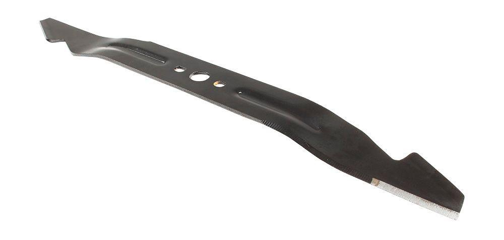
Now that the blades are the only thing missing on the robot mower, I’m realizing how mistaken that assumption is. I designed the mower deck for three 12in long blades, thinking that surely such a size exists. But most blades are generally in the neighborhood of 20in long.
Small gasoline powered mower engines operate at speeds in the range of 2,500RPM to 3,000RPM, and to achieve an appropriate blade tip speed slightly less than 19,000ft/min, the math forces you to use a blade that is between 19in to 22in long. Blade sizes outside this range aren’t common.
Initially I decided this wasn’t an issue: I’ll just make my own blade. It’s just bar stock with two sharp edges, right? Well, kind of. There’s a fair amount of metallurgical considerations that go into mower blade fabrication. On the one hand, you want a soft, ductile blade that doesn’t shatter when it hits a rock or tree stump. But on the other, you want the blade to be able to keep a sharp edge for a long time, which means making the blade, at least near the sharp edge, more brittle.
Cutting grass creates an inherently moist environment under the deck, so mower blades are usually painted or feature some kind of corrosion resistance. And on top of all this, a good blade will have a small bend opposite the cutting edge to create a little wing so that the grass clippings can be pulled upward resulting in a nice, even height cut.
The more you learn about mower blades the more you start to realize that buying one is really the way to go. In your research you’ll come across horror stories of guys who made their own mower blades and either welded them poorly or jury rigged them to work and then got hurt or even killed by the shrapnel from a blade shattering. Just this video alone should give you pause: there’s a lot of energy under a mower deck.
So off I went to find a 12in long mower blade. The closest I could find was one that was 12.125in long, which leaves 0.375in between the blade tips when they rotate past each other instead of the 0.625in I had designed for. We’re about to find out how accurately the mower deck weldment was made. I really hope I don’t have to grind the ends of the blades down because they crash into each other.
Finding a blade is only half the battle. How do you attach it to the 0.5in diameter keyed shaft on the E30-400 motor? The crankshaft on most push mowers I’ve seen has a threaded hole in the shaft for bolting the blade on. The E30-400 has nothing of the sort.
Could you drill and tap a hole in the end of the shaft? Possibly. But a #10-24 threaded hole is about the biggest you could drill and tap, and that only gives you 0.083in of edge margin from the major diameter of the threads to the keyed portion of the shaft. Too close for comfort in my mind.
The first solution that I came up with was to take a piece of 1.5in long, 2in diameter round stock, bore a 0.5in hole in it, key the hole, and then drill and tap holes for mounting the blade and some set screw holes to clamp the key up against the shaft. But in this scenario, the set screws are the only thing that holds the blade on the shaft. Better than nothing, but not by much.
I got a few quotes on three of these parts and the keyway really kills you on cost. I got several no bids because of the keyway alone. And the quotes I did get back were pretty high. Because I don’t like spending $300 on blade adapters, it was back to the drawing board.
What I really need is something with a keyway already in it. Initially I looked into some keyed pulley bushings, but they too have no way to hold themselves on the shaft. That and they have to match your hole pattern on the blade, and none of them met that criteria. They’re cheap, which is nice, but don’t really work for this purpose.
Eventually I got turned onto the idea of using solid shaft couplings. They’re keyed and include set screws. But the outer diameter for most half inch couplings is 1.5in or larger. That leaves no clearance for the bolts to mount the mower blade, which are 1.625in apart.

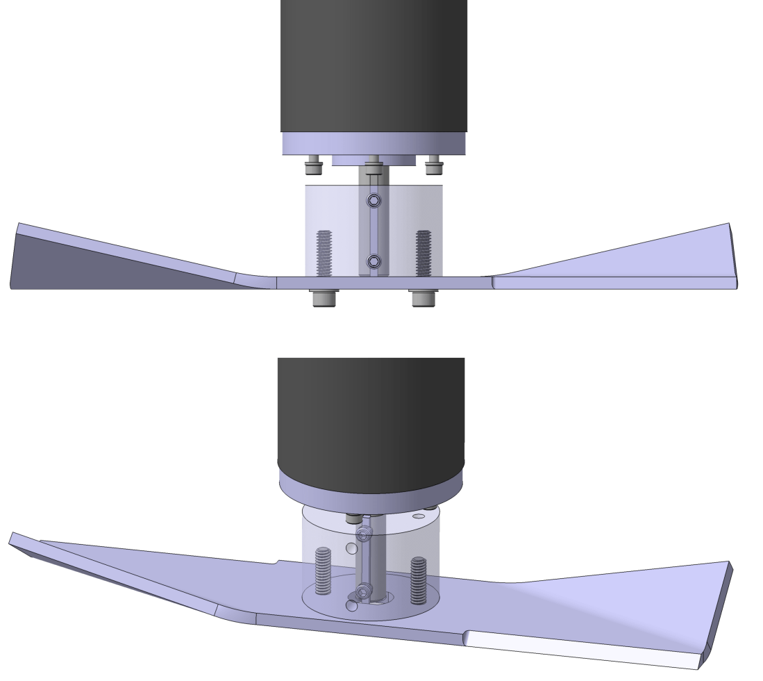
After some more digging, I found these smaller OD shaft couplings. And on top of their 1in outer diameter, they come with 2 pairs of set screws offset by 90°. Not bad! Take one of them and weld it to a plate with a hole pattern matching your mower blade, and you’ve got a custom mower blade adapter for ~$30 a piece after material and labor. The result looks like this:
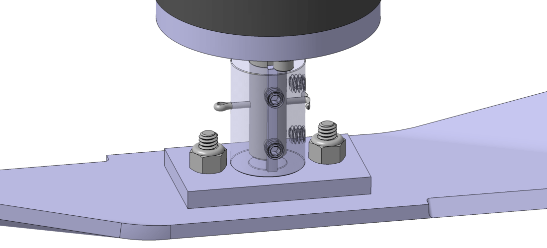
The nice thing about the plate is that you can get a lock nut on the back side. I’m less worried about things vibrating loose compared to the machined adapter where the bolts run straight into a threaded hole.
But even with four set screws clamping up against the shaft, you really need some positive retaining feature to make sure the blade stays on the shaft. To meet this design objective, I figured it’s best to keep things simple: drill a small hole perpendicular to the coupling and the motor shaft, and then run a small hairpin through it. You don’t need a big one to keep it on the shaft.
The hairpin will add a little bit of eccentricity, as will the set screws. How much? I guess we’ll find out soon. Once the parts get back from the shop I’ll post some graphs and pictures.

Thanks for the timely article:) I’m not sure about that mechanism for keeping the blade on the shaft. There is a lot of energy as you say. If that shaft bolts loosen then I’m not sure the pin will hold it. I feel uncomfortable with this motor shaft setup. I think a slightly larger motor shaft with a bolt is the way to go?
LikeLike
Hi don13, your comment on a previous post pushed me over the edge to make this one. These are things I’ve been working on lately but didn’t think were interesting enough to post about. Thanks for convincing me otherwise!
When you say “shaft bolts”, are you referring to the set screws in the coupling that press against the shaft? If they do loosen up, you are correct, the only thing that keeps the coupling from sliding off the shaft is the cotter pin.
However, I think the pin will be more difficult to shear off than you’d expect. It’s not loaded in shear from the rotation of the blade. The key between the motor shaft and coupling takes that load. Only force parallel to the shaft axis will create a shear load on it.
I plan on using a 0.125in diameter cotter pin in this area. If it’s made from a low grade 1000 series steel with a tensile yield strength of 24000psi, then the force to shear it apart is:
Shear Force = (0.577)(24000psi)(3.14)(0.0625in)^2 = 170lbf
That’s for single shear, now that I think about it, it’s actually in double shear so it could take twice that force before failing.
I really like your suggestion of using a larger motor shaft. That would simplify things greatly. But unfortunately, the tradeoff for getting a larger shaft means paying for a larger, more powerful motor than is even remotely necessary. You’d get a shaft diameter that’s easier to work with, but you’d be looking at RPMs and torques that are way outside of what is necessary for this application.
My biggest concern is one raised by Sean below, vibration. This whole thing could fly apart if there’s too much vibration, and when you’re spinning at thousands of RPMs there’s going to be some vibration.
I’m very open to ideas on how to improve this area of the mower, I think this solution will work and will be safe provided reasonable amounts of vibration, but it’s definitely messy. How would you approach it?
Thanks again for your comment,
-Mister Mower
LikeLike
What about weight and balance of the blade itself relative to the mount its on? The forces of it spinning just of tilt could destroy the whole thing. I think this part of it scares me a bit for you.
LikeLike
That’s an excellent question Sean. The shop that’s making the adapters is going to machine the bottom of the adapter plate so that it is perpendicular to the axis of the shaft coupling.
But eccentricities will exist from the set screws and cotter pin. I’ll probably have to build the whole thing and then balance the blades like you would on a push mower.
LikeLike
Instead of using rotary mower blades, have you considered experimenting with the automower razor blade disc setup? You could much easier test that configuration out with 3, 4, 5 etc blades per rotating disc, plus you will have significantly more torque from these motors for even better cutting action. You might consider experimenting with that setup first and seeing what kind of cutting you get. In theory you will be able to to mow more frequently since the robot does the work so need larger blades shouldn’t be a requirement. Also in my own experience ( I have a reel mower, push mower and husqvarna automower) the cut quality of the automower blades are much cleaner than the chopping action from the rotary, very close to a reel mower.
LikeLike
If that blade ends up being too long, here is a 11-7/8″ long blade that could possibly work for you: https://www.mfgsupply.com/15-6093-husqvarna-506-6687-01.html
LikeLike
Thanks for the tip Nick, I’ll keep this in mind if I can’t get my hands on some 91-802 blades.
LikeLike
Hi,
at our web page please find information about our RTK/GPS mower project:
We have connected to a existing mower.
LikeLike
Very nice! I will need to block off an hour or two to really spend some time reading over your website Bjorn, there’s a lot there to peruse. Thanks for dropping by!
LikeLike
Check out this motor…
https://www.alibaba.com/product-detail/Durable-Using-Low-Price-115-85mm_1600072758529.html?spm=a2700.galleryofferlist.0.0.3d4b3d8c5V15VF
LikeLike