Wiring Improvements

I’ve spent most of this winter re-wiring the robot mower. In hindsight, I should have spent a lot more time planning the wire runs. I made a lot of design choices about how the chassis should look and where enclosures should be located that are inappropriate given my more complete understanding of how the wires need to be connected between components.

At some point you have to build something that’s not perfect and work through the bugs later. It’s against my nature to operate that way, but if I hadn’t started building the robot mower in reality at some point, it would still be a picture in my CAD program.

In the rest of this post, I’ll describe some wiring related improvements I’ve been making to the robot mower.

The original power enclosure. The phrase “rat’s nest” comes to mind.

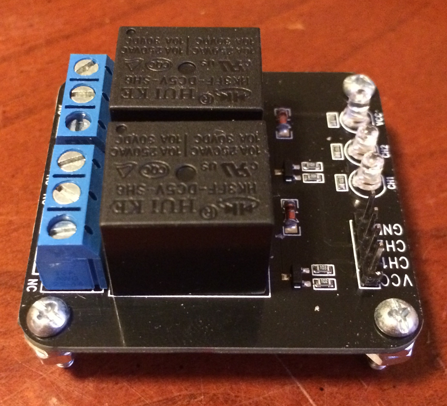
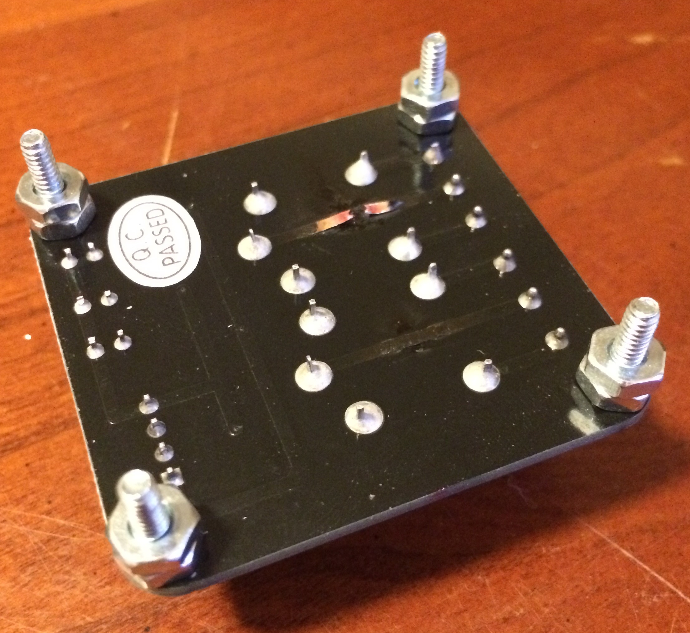
The picture above is how the power enclosure used to look. It used to contain the Sabertooth 2X60, the voltage/current sensor, the BEC, a positive and negative terminal stud, a small 5V relay board to trigger two larger 50A relays, a power switch and an XLR charging port. It was a mess, to say the least.

The reorganized power enclosure. No relays or terminal studs, just two motor controllers and a BEC.

The reorganized enclosure contains the Sabertooth 2X60, the BEC, power switch, XLR charger port, and a motor controller for the deck motors exclusively.

The reason I tried to pack so many components into the power enclosure was so I didn’t have to put anything other than wires in the battery bay. It is a battery bay, after all. I was hoping to make an entirely modular power enclosure I could build up separately from the robot and then basically bolt on.

While that’s nice in the CAD software, in reality it didn’t work. If I’d selected a larger enclosure it might have been possible. But an unintended side effect of putting everything in one enclosure is that you have to run 24V and ground into the enclosure, but you then turn right around and run a ton of wires right back out of the enclosure.

As I have learned, relays are not a great way to control motors, especially if they’re using a lot of power. And on top of that, those “200A” relays were kind of a scam. They terminals are only rated for 50A, and I’m pretty sure I managed to fry one out in the field. I decided to replace them with a single channel motor controller that can supply up to 200A of current.

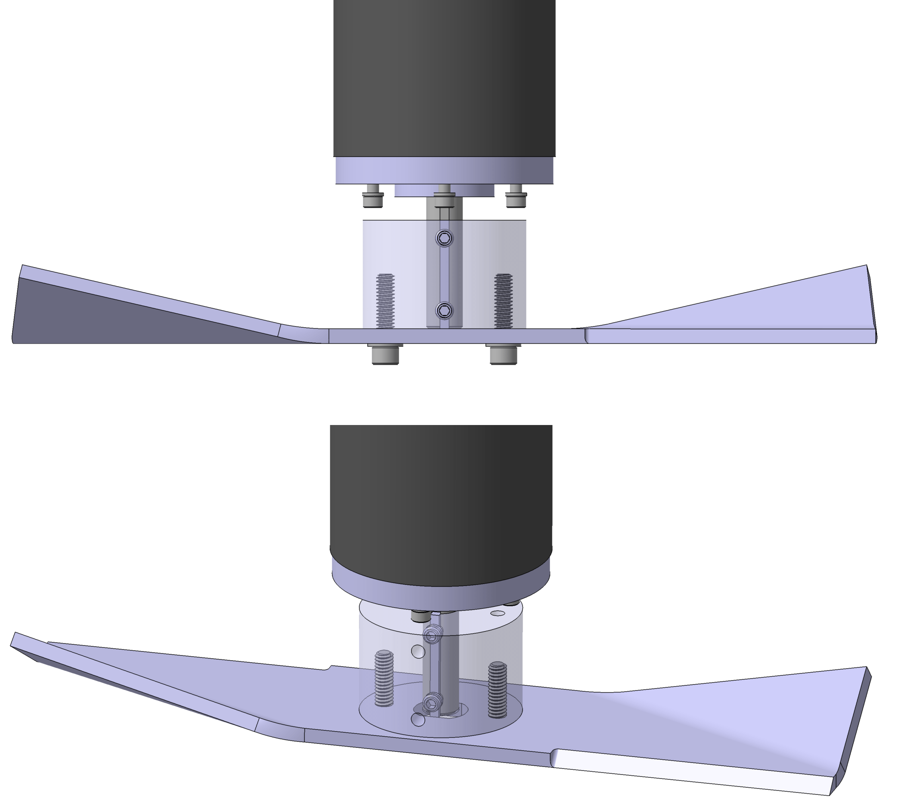
The nice thing about having a motor controller driving the deck motors is that I can dial back the blade speed if the mower is cutting the grass just fine. There’s no sense in running at 4800RPM when 3600RPM will do the job. I’m hoping this will allow the robot mower to run for a longer period of time.

A fuse block for the mower deck motors.

I was using wire nuts to connect all of the deck motor wires together originally. I wanted to make things a little more professional than that, so I decided to replace the wire nuts with a fuse block.

In theory, the deck motors should only use about ~30A each at steady state, and with the new motor controller, I think I can spool them up slow enough to where a fuse doesn’t blow. We’ll see how good this assumption is soon.

One thing I like about the fuse block is it allows me to easily disconnect power from the deck motors: just pull the fuses. This makes safe troubleshooting easier. The fuses will also provide a layer of protection for the motor controller. But at the same time, a blown fuse creates exactly the situation that caused my wire failure. I intend to also have a Zener diode between the supply terminal and ground to hopefully protect against this situation, too.

Components relocate into the battery bay. From left to right, there’s an RC controlled relay board, a solenoid, the voltage/current sensor, and a master fuse block.

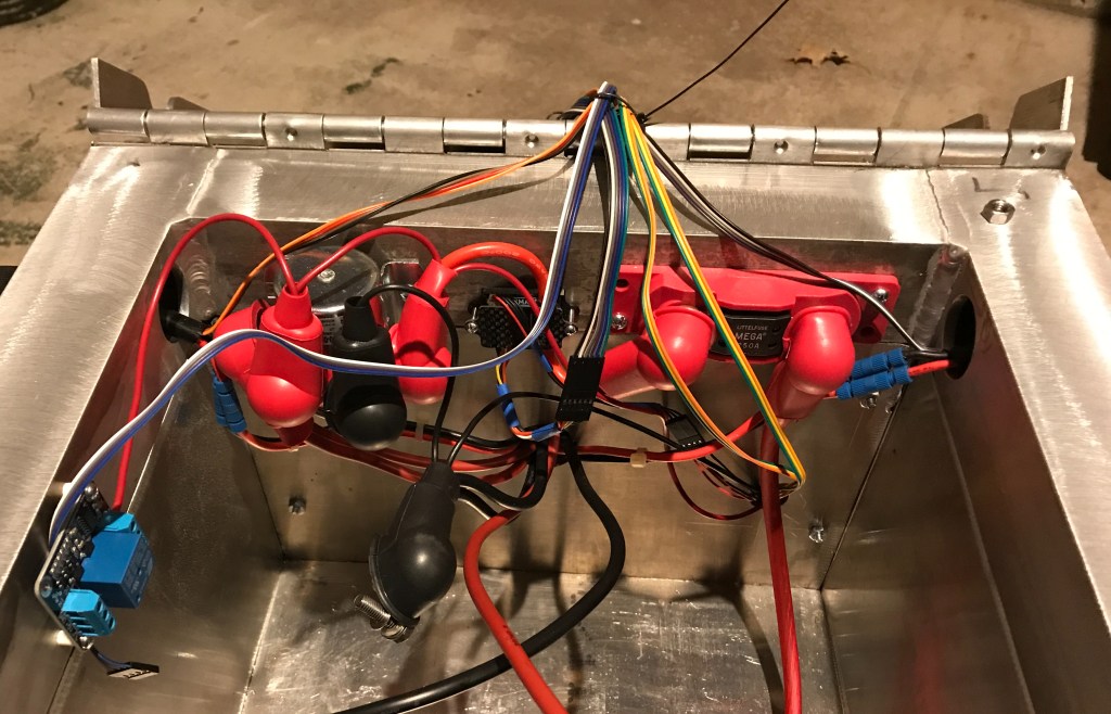
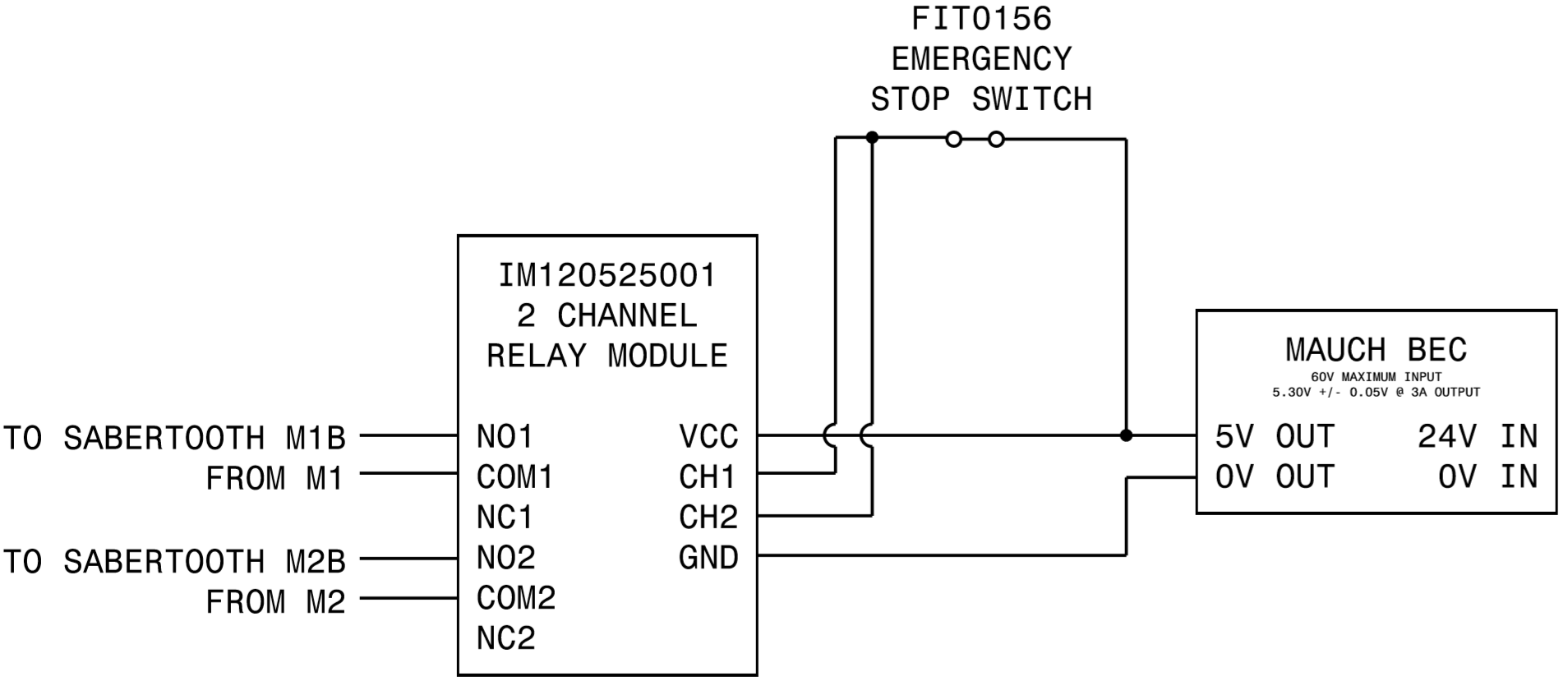
All of the power in the robot now runs through a MEGA fuse, and from there it runs through the voltage/current sensor. After that, it runs through a solenoid, which supplies power to the drive and deck motor controllers. The solenoid can only be powered if the E-stop switch and RC relay board are in safe states.

I also put rubber boots on every exposed terminal, including the batteries. They look a little ridiculous on that solenoid, but they are adequately insulated.

The RC controlled relay board.

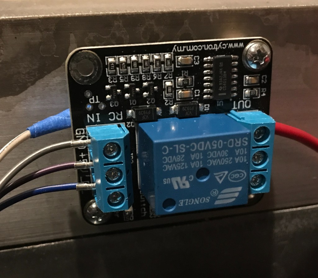
The RC relay board is controlled by a switch on the RC transmitter. If the RC relay board doesn’t detect a valid RC signal, it will open the relay. This allows me to have a remote E-stop switch.

One thing I don’t like about this RC relay board: when you power it on, it automatically closes for a second, then goes open. That’s a really crappy design, in my opinion. But without the Pixhawk armed it’s kind of a moot point.

A proper ground plane for the GNSS antennas. The foil to the left was what was underneath the RTK GNSS receiver previously.

I also finally got around to putting a proper ground plane under my GNSS antennas. We’ll see how much this improves performance.

I hope to have these wiring improvements wrapped up soon. The grass is green and growing out here in Kansas!

How Not to Wire Up a Robot

What could have been the ignition source for a Kansas grass fire.

If you look closely at the charts in the previous post, you’ll notice they end quite abruptly. The picture above shows why.

I have the robot mower configured so the blades only turn on when you hold the rudder stick to the right. The stick is spring loaded, so letting go of it returns it to center, deactivating the blades.

A typical shrub out in the field. Most were about 18in tall.

The field I was testing in had several large shrubs in it. One of my goals in the field was to push the envelope on what the mower was capable of cutting through, so I let it mow over several of them in autonomous mode. However, there was a particularly large shrub in the robot’s path, and so I decided to turn the mower blades off by releasing the rudder stick.

As expected, the blades stopped. But the robot stopped moving, too. This was curious: the robot should have continued driving. So I pressed the emergency stop button on the robot to immobilize it, and walked over to the truck where I had Mission Planner running on my laptop.

A screenshot of Mission Planner telemetry log after I returned to the truck. The reported voltage is 12.50V.

The Mission Planner screen was frozen as if it wasn’t receiving telemetry from the robot. It took me a few minutes to realize that the issue wasn’t Mission Planner or my laptop radio: it was that the robot wasn’t sending telemetry. And even more curiously, the voltage reading on my SLA batteries said 12.50V. I was worried that I’d really fried my batteries, so I walked back over to the robot to investigate.

Opening the battery bay I found a slight amount of smoke and that awful burnt plastic smell from melted wire insulation. But other than that everything seemed fine. There wasn’t a smoldering fire inside the robot. The batteries weren’t hot to the touch.

At first I chalked it up to too much current running through the wires. The robot uses 120A at peak current, and at those levels even a small amount of resistance could cause the wires to heat up a lot. Perhaps the wires just got hot enough to melt the insulation and came into contact right at the moment I decided to shut the mower blades off?

One of the melted wires. The yellow blob on the end is a portion of a Posi-Lock.

This just so story didn’t sit well with me. What an awful coincidence that the wires failed at exactly the same moment I was shutting off the motors, especially after the robot ran fine for five minutes prior. Why didn’t they fail earlier?

Additionally, why didn’t the exposed wire conductors fuse together after they came into contact? I’ve heard of people using SLA batteries smaller than mine to spot weld 18650 battery tabs together. The wires were really close together, but weren’t touching when I opened the battery bay. And the wire strands don’t seem to be melted judging from the picture above. Which was extraordinarily lucky, given how bad that could have been.

I did have enough sense to put a 100A fuse on my batteries. It seemed logical that the fuse was what saved my bacon. But using the multimeter to test the fuse revealed that it was not, in fact, blown. At this point I was completely bewildered. I thanked the good Lord that the robot hadn’t turned into a massive lead acid fireball, made sure all my batteries were all disconnected, packed up, and went home.

I’m sure readers are ready to scold me for all of the janky things going on in my battery bay, and I certainly deserve that criticism. My mantra is make it robust, and I definitely did not live up to that standard with my wiring. Below is a full picture of the battery bay.

The robot mower battery bay. How many janky things can you spot?

I have my own list of janky things in here that I intend to fix. What do you see that is janky? Feel free to comment below!

In the next post, I’ll explain what I think went wrong, and the improvements I’m going to make to mitigate the problem and eliminate all the redneck wiring I’ve got going on.

Mower Blades: More Complex Than You’d Think

ego-lawn-mower-blades-ab2000-64_1000
A typical mower blade.

While designing the robot mower, I spent a lot of time working on the chassis, electronics enclosures, and wire routes. I tried hard to select components I could easily acquire at a reasonable cost, and that effort paid big dividends when I went to get everything built.

Unfortunately, I didn’t spend nearly as much effort on how the mower blades would attach to my motors, or even what the mower blades would look like. I assumed I could easily find any mower blade size I would need, or that making my own custom blades wouldn’t be difficult.

Now that the blades are the only thing missing on the robot mower, I’m realizing how mistaken that assumption is. I designed the mower deck for three 12in long blades, thinking that surely such a size exists. But most blades are generally in the neighborhood of 20in long.

Small gasoline powered mower engines operate at speeds in the range of 2,500RPM to 3,000RPM, and to achieve an appropriate blade tip speed slightly less than 19,000ft/min, the math forces you to use a blade that is between 19in to 22in long. Blade sizes outside this range aren’t common.

Initially I decided this wasn’t an issue: I’ll just make my own blade. It’s just bar stock with two sharp edges, right? Well, kind of. There’s a fair amount of metallurgical considerations that go into mower blade fabrication. On the one hand, you want a soft, ductile blade that doesn’t shatter when it hits a rock or tree stump. But on the other, you want the blade to be able to keep a sharp edge for a long time, which means making the blade, at least near the sharp edge, more brittle.

Cutting grass creates an inherently moist environment under the deck, so mower blades are usually painted or feature some kind of corrosion resistance. And on top of all this, a good blade will have a small bend opposite the cutting edge to create a little wing so that the grass clippings can be pulled upward resulting in a nice, even height cut.

The more you learn about mower blades the more you start to realize that buying one is really the way to go. In your research you’ll come across horror stories of guys who made their own mower blades and either welded them poorly or jury rigged them to work and then got hurt or even killed by the shrapnel from a blade shattering. Just this video alone should give you pause: there’s a lot of energy under a mower deck.

So off I went to find a 12in long mower blade. The closest I could find was one that was 12.125in long, which leaves 0.375in between the blade tips when they rotate past each other instead of the 0.625in I had designed for. We’re about to find out how accurately the mower deck weldment was made. I really hope I don’t have to grind the ends of the blades down because they crash into each other.

Finding a blade is only half the battle. How do you attach it to the 0.5in diameter keyed shaft on the E30-400 motor? The crankshaft on most push mowers I’ve seen has a threaded hole in the shaft for bolting the blade on. The E30-400 has nothing of the sort.

Could you drill and tap a hole in the end of the shaft? Possibly. But a #10-24 threaded hole is about the biggest you could drill and tap, and that only gives you 0.083in of edge margin from the major diameter of the threads to the keyed portion of the shaft. Too close for comfort in my mind.

The first solution that I came up with was to take a piece of 1.5in long, 2in diameter round stock, bore a 0.5in hole in it, key the hole, and then drill and tap holes for mounting the blade and some set screw holes to clamp the key up against the shaft. But in this scenario, the set screws are the only thing that holds the blade on the shaft. Better than nothing, but not by much.

combined
My first idea for a mower adapter: a machined piece of round stock. Expensive and heavy, not what you want in a blade adapter.


I got a few quotes on three of these parts and the keyway really kills you on cost. I got several no bids because of the keyway alone. And the quotes I did get back were pretty high. Because I don’t like spending $300 on blade adapters, it was back to the drawing board.

What I really need is something with a keyway already in it. Initially I looked into some keyed pulley bushings, but they too have no way to hold themselves on the shaft. That and they have to match your hole pattern on the blade, and none of them met that criteria. They’re cheap, which is nice, but don’t really work for this purpose.

Eventually I got turned onto the idea of using solid shaft couplings. They’re keyed and include set screws. But the outer diameter for most half inch couplings is 1.5in or larger. That leaves no clearance for the bolts to mount the mower blade, which are 1.625in apart.

IMG_6250
A 0.5in ID X 1in OD solid shaft coupling with four set screws. McMaster has them for $16 apiece, but if you search on eBay you can find them closer to $6.

After some more digging, I found these smaller OD shaft couplings. And on top of their 1in outer diameter, they come with 2 pairs of set screws offset by 90°. Not bad! Take one of them and weld it to a plate with a hole pattern matching your mower blade, and you’ve got a custom mower blade adapter for ~$30 a piece after material and labor. The result looks like this:

the best option
The 1in OD shaft coupling welded to a plate. The cotter pin keeps the coupling on the shaft.

The nice thing about the plate is that you can get a lock nut on the back side. I’m less worried about things vibrating loose compared to the machined adapter where the bolts run straight into a threaded hole.

But even with four set screws clamping up against the shaft, you really need some positive retaining feature to make sure the blade stays on the shaft. To meet this design objective, I figured it’s best to keep things simple: drill a small hole perpendicular to the coupling and the motor shaft, and then run a small hairpin through it. You don’t need a big one to keep it on the shaft.

The hairpin will add a little bit of eccentricity, as will the set screws. How much? I guess we’ll find out soon. Once the parts get back from the shop I’ll post some graphs and pictures.

Lawn Mower Safety Regulations: A Brief History

Wednesday May 7, 1977 was a cloudy day in Gaithersburg, MD. Shortly before lunch that morning, several engineers and inventors entered building 202 on the National Bureau of Standards campus. They came from all over the country to present mower safety devices they’ve designed to the newly established Consumer Product Safety Commission (CPSC), created by the Consumer Product Safety Act (CPSA) signed into law by President Nixon 5 years earlier.1

A month prior to this meeting, the CPSC voted to implement a new safety standard for power lawn mowers.2 They were looking for the cutting edge in lawn mower safety technology, and hoped to find new safety ideas by meeting with individuals and manufacturers who were innovating in this realm. The ideas gathered at this meeting influenced parts of the new lawn mower safety regulation, known today as 16 CFR Part 1205: Safety Standard for Walk Behind Power Lawn Mowers.3

The origins of 16 CFR Part 1205 are quite convoluted. In August 1973, the Outdoor Power Equipment Industry (OPEI) petitioned the CPSC to adopt ANSI B71.1-1972, the most recent ANSI safety standard for power mowers, as the CPSC’s safety regulation for walk behind lawn mowers. But for reasons unknown, in October 1974, the CPSC instead contracted with Consumers Union (CU) of United States, Inc., today known as Consumer Reports, to propose their own regulation. The CPSC paid $66,745 to CU to develop the standard, in addition to another $25,000 for experimentation and testing.4

With these funds, CU conducted significant research to develop their proposed regulation. They organized time studies to see how fast an operator can move their hands from a power mower handle to underneath the mower deck. They examined the forces blade shields would encounter during typical mower operation. They gathered and compiled existing research on lawn mower injuries, combined it with their own research, and presented it to the CPSC along with their proposed regulation.

CU’s recommended regulation contained several detailed safety rules for preventing electrocution from mower electrical systems, burns from hot mower surfaces, hearing loss due to excessive mower noise, impact from debris thrown by the mower, shields for exposed mower blades, and mower start and stop controls, while addressing other safety issues.5

While the CPSC didn’t use every recommended rule written by CU, it did adopt several rules related to maximum blade stop time, mower start and stop controls, and mower shields and guards. These rules, in addition to new labeling and record keeping requirements, form the newly promulgated 16 CFR Part 1205, which was placed in the Federal Register on February 15, 1979, with an effective date of June 30, 1982.3

But before the new regulation could go into effect, the OPEI sued the CPSC. In Southland Mower v. Consumer Product Safety, the OPEI’s lawyers make any and every argument they can think of to nullify, neuter, or otherwise delay the regulations in 16 CFR Part 1205.5 They argue that lawn mowers are not consumer products, and hence the CPSC does not have authority to regulate them. They argue that there is insufficient evidence in favor of a safety regulation, and that it violates the CPSA. They argue that new shielding requirements will be defeated by consumers and are not efficacious in promoting safety. The majority of their arguments are pedantic and relate to interpretation of the language of the CPSA and how it pertains to 16 CFR Part 1205.

The case is heard by the Fifth Circuit Court of Appeals, and on June 19, 1980 they hand the OPEI a sound defeat based on the CPSA’s broad language allowing it to regulate, well, consumer products. It does, however, throw the OPEI a bone by vacating a portion of the regulation’s foot probe requirement, stating insufficient evidence exists to prove it will reduce foot injuries as a result of contact with a rotating mower blade.

Within the text of 16 CFR Part 1205, the CPSC notes that many mowers on the market in 1980 already feature the safety devices mandated by the regulation. In effect, the regulation codifies what most manufacturers are already doing regarding mower deck shields and controls, but includes new record keeping and safety labeling requirements. And, as with all regulations issued by the CPSC, there are new penalties for non-compliance.

The CPSA mandates safety regulations define performance requirements6, not design requirements. The idea is that regulations should promote multiple creative solutions to a safety problem, not mandate a single specific solution. But 16 CFR Part 1205 mandates the geometry of shields and the specific location of mower controls. There are only so many ways you can design a shield or locate a dead man switch to satisfy the regulation.

And as a result, innovation in the power mower realm decelerates after the 16 CFR Part 1205 goes into effect. In many ways, the regulation froze the state of the art in safety technology for mowers in the early 1980’s. Power mowers manufactured today are remarkably similar to those made from that era.

With decades of injury data to examine, an argument can be made that 16 CFR Part 1205 hasn’t even improved mower safety. At the time it was issued, the CPSC estimated 77,000 mower related injuries occur annually. Between 2005 and 2015, that number is estimated at more than 84,000 annually.7 The severity of these injuries may be less, but as an empirical fact, more people are injured by power lawn mowers today than before the regulation was put into effect.

One can only speculate what the inventors who met to showcase their safety innovations in Gaithersburg, MD would have thought about the resulting safety regulation their ideas influenced. But it’s a safe bet each of them would probably agree: if you want to prevent mower injuries, find a way to separate the operator from the mower. Next time I’ll talk about how 16 CFR Part 1205 makes that difficult, and how the regulation has influenced mower design ever since its inception.

References

  1. CPSC Invites Inventors of Lawn Mower Safety Devices, CPSC.gov, 11/16/19.
  2. CPSC Seeks Offerors to Develop Mandatory Power Mower Safety Standards, CPSC.gov, 11/16/19.
  3. 16 CFR Part 1205, govinfo.gov, 11/16/19.
  4. CPSC Accepts Consumers Union Offer to Develop Power Lawn Mower Safety Standard, CPSC.gov, 11/16/19.
  5. Southland Mower v. Consumer Product Safety, 619 F.2d 499 (5th Cir. 1980).
  6. Consumer Product Safety Act, Section 7(a)(1), CPSC.gov, 11/16/19.
  7. Lawn mower injuries presenting to the emergency department: 2005 to 2015. NCBI, 1/10/18.

The Culprit

IMG_4307
The dual channel relay module. The module features two 30VDC, 10A relays soldered to the board. Each relay can be triggered independently with 5V applied to the appropriate header.

It appears the root cause of the right motor not responding at all to RC input was actually a lot simpler than I imagined. I should have caught it early, and the fact I didn’t is a little embarrassing.

Mission planner usually says that the motors are drawing approximately 5A to 7A so I generally assumed the motors weren’t under that much load. I am now questioning those readings given the damage to the board, shown below.

IMG_4308
The bottom of damaged relay board.

I remember checking the relay board after one of the motors stopped working, but I was relying on the LEDs to confirm the relay was triggering properly. This was the wrong way to check the board, because the LEDs light up when 5V is applied to the header pins, not when the relay actually closes.

I also seem to recall hearing the relay “click” when triggered, but because the wire trace in the board was burnt up, no current could flow through the board, whether the relay was engaged or not. Because the back of the board was hidden and I couldn’t see the burnt up wire trace, I assumed the relays were good and moved on. I’ll check the module later, but the relays probably still work fine.

Lessons Learned

My Mission Planner current readings are probably wrong.

I don’t think I have the current sensor calibrated or configured properly. Either that, or mission planner does some kind of smoothing of current measurements that doesn’t reveal maximum current flow, only the average over the measurement period. The Mission planner output is total current consumed by the robot, meaning 7A is used for everything. This shouldn’t have caused a problem, in theory. Obviously, there is a disconnect between reality and theory somewhere.

You get what you pay for.

This relay board was $3 plus shipping. The header pins were a nice setup, and the fact that the relays could be triggered with 5V is the main reason I bought them. I had a convenient 5V source to switch them with, so I tried to keep things simple. Unfortunately the board was undersized for the task, as you can even see heat damage to the conductor that isn’t completely split. I should have known there was a problem when I couldn’t fit 12ga wire into the screw terminals on the board and had to use 16ga wire instead. Not good.

Fuses are critical for protecting components and preventing fire.

I’ve been skeptical of going to the trouble of putting fuses in my robot, partly from a cost perspective but mostly from an “ain’t nobody got time fo dat” mentality. This failure could have been a more critical component. If the relay board hadn’t failed, I could have fried the Sabertooth, or worse, started a fire in the enclosure. While I’ve focused my safety efforts on the spinning blades, this is an equally important area to get right.

Remember Occam’s Razor when troubleshooting.

When one motor spins but the other one doesn’t, which is more likely:

  1. The Sabertooth motor controller is fried, but only halfway fried.
  2. There’s a connectivity problem to the motor that doesn’t turn.

Taking a step back to asses the problem can save a lot of useless troubleshooting, like tearing the Sabertooth out and testing it. Use common sense. Start checking the simplest failure modes first, moving to more complicated failure modes until the root cause is found.

Going Forward

To switch current to the motor controller I am going to add a much larger 50A relay to this system. I’ll then use one of these smaller boards to switch the 50A relay. The coil current consumed by the 50A relay should be much lower than the current consumed by the drive motors on the robot.

The Emergency Stop Switch

This weekend I had some time to install my emergency stop switch. At first I thought I would keep things simple and just mount the emergency stop switch on top of the control enclosure and route one of the battery wires straight through the safety switch. Sounds simple, right? This method, however, presents two big issues:

  1. Hitting the emergency stop switch shuts power off to the entire rover.
  2. A high current carrying wire has to run through the control enclosure.

The first item above is an issue because we want to be able to communicate an emergency shut down state to the ground control laptop. If all the power is shut off to the rover, a power failure and an emergency shut down will appear identical from the ground control’s perspective.

The second item is an issue because it defeats the purpose of separating the power and control electronics. The constraint here is that the emergency stop switch has to be mounted on top of the control enclosure so it is visible, accessible, and in a safe location, but we can’t have a high power wire running through it. We want to keep those noisy high current wires away from sensitive electronics.

The solution? A relay! Or more specifically, a set of relays. We’ll have the emergency switch trigger a relay that cuts power to the drive motors only in an emergency state. We’ll also keep all the high current wires contained to the power enclosure.

Safety System
The wiring diagram for the emergency stop system.

The FIT0156 emergency stop switch has two integral switches triggered by the big red button. One is NC and the other is NO. Our system uses the NC switch. When the button is pressed, the switch opens and prevents 5V from flowing to the CH1 and CH2 pins on the relay module. This opens the motor circuit, immobilizing the rover.

The IM120525001 2 channel relay was only $3, but I wasn’t sure if it would be large enough to conduct the current needed by the motors. I decided to take a gamble, and I’m glad I did. The module works very well. The spec sheets say it can conduct up to 30A at 24VDC. The only drawback is that the screw terminals on the module aren’t big enough for 14 gage wire. I had to use 16 gage wire instead.

I measured current flow between the 5V output on the Mauch BEC and VCC on the IM120525001 module and my ammeter said it consumes 170mA, a little bit high for my liking, but manageable. The Mauch BEC is rated for 3A, so it shouldn’t be a big issue.

I oversized both enclosures knowing there would be additional things I add later, and I am glad that I did. The emergency stop switch and relay module both fit nicely in my enclosures.

Relay
The power enclosure with the relay module mounted nicely in the lower right. Both of the motors have one wire routed through the relay module before connecting to the Sabertooth motor controller.

I used one of my remaining 8 pins on the DB15 breakout board to route the emergency stop switch down to the power box. This wire goes to both the CH1 and Ch2 pins on the relay module. When you hit the button both motor circuits are opened.

IMG_3956
The big red button installed on the rover. Be sure to include large, clear signage stating that this is how you shut it off!

So the total cost of our emergency system:

  1. Emergency stop switch, $6
  2. Relay module, $3
  3. Emergency stop sticker, $2
  4. Miscellaneous wire, $1

Tack on a few dollars for shipping and sales tax for those items and you’re still easily under $20. Not too shabby.

Safety First!

Eventually the rover will have a spinning blade of death on it. Before we get to that point we need to include some safety mechanisms. Let’s be real: these features aren’t just for innocent bystanders. You’re the one tinkering with this thing. Do yourself a favor and invest in some simple safety features. They don’t have to be expensive or complicated.

0CQKa7d
Safety is your responsibility! Only you can keep this adorable kitty cat safe.

The goal of a safety system is to ensure that at all times the rover is in a safe state. What is a safe state, you ask? Well, that depends. Say the spinning blade of death is barreling toward a small kitten. A safe state would be one in which it stops barreling toward that kitten. So tell the motors to stop spinning, right?

Well, maybe. But what if the rover is on an incline, and could start rolling backward? That’s certainly not safe. Well, then put the brakes on, you may say. Sure, that might work. But what if you already hit the kitten and the poor thing is stuck under the spinning blade of death already? Now what?

The above scenario may seem preposterous, and it is unlikely. But it illustrates an important point: you need to be proactive about identifying safety risks. 

Safety system design is a whole discipline in itself, but there’s one thing we can all agree on: a safe state is one in which the spinning blade of death stops spinning. So let’s add a simple emergency stop switch to shut off the spinning blade of death.

Right now our rover isn’t equipped with such a feature, but we can wire it into the drive motors so that when you hit the emergency stop switch, the rover stops moving. Down the road we’ll also wire it into the motor powering the mower blade.

emergency-stop-switch-1
The big red button. Nothing screams Emergency Stop like that danger red.

So what goes into an E-Stop?

I don’t need an emergency stop switch. I have an on off switch and I’m smart enough to know how to use it.

-Me, before the rover slams into my shin

For an emergency stop switch to do any good, it needs to be identifiable. Think you’re on off switch is good enough? It may be for you, but can a person who has never seen your rover before identify it? Possibly, but we can’t assume that. Our emergency stop switch needs to be a big red button with a giant label by it saying Emergency Shut Off Switch or something of that nature. This way your grandma could easily figure out that this button will turn off the spinning blade of death.

Your E-stop also needs to be accessible. This means that it can be easily pressed by anyone. It’s not on the back side of your rover near the bottom. It’s front and center, located in an area where a person could quickly press the button if your rover were coming right at them. Set it at a height that your 4 year old niece could reach if your rover is of any significant size. What good is an E-stop if it can’t be reached?

Related to making your E-stop accessible, be sure to put it in a safe location. I know, that sounds awfully obvious, but be cognizant of what’s around your button. Is there a hot surface near it? Bad place for your E-stop. Is it near your spinning wheels? Also a bad place. Use common sense.

Lastly, your E-stop should put the rover into a safe state. What that looks like depends uniquely on your situation. In this case, it means the motors are de-energized.

Next time I’ll show what this kind of system looks like for the rover V2.