I didn’t spend much time in the field testing the robot mower, but the little time I did spend gave me a treasure trove of information about how the robot mower performs. Below are some high-level measures.
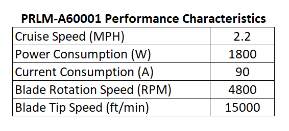
I set the robot cruise speed to 1m/s or 2.2mph. I’ve run the robot mower faster in manual mode, but for obvious safety reasons, a moderate walking pace seemed best. If the robot gets out of control, I want to be able to catch it.
I am using a Mauch PL-200-HV current sensor on the robot. The sensor is connected to the positive terminal on my batteries, so it reports the total current used by robot: sensors, drive wheels, mower deck motors, etc. Once the mower is spooled up, current consumption levels out at about 90A.

The first portion of the graph above is the robot mower operating autonomously without the deck motors turned on. The huge spike is when the deck motors get turned on. It’s curious it says the peak is 196A: the PL-200-HV is only rated for 200A. I wonder if the spike was actually larger than shown, but due to its current rating, the sensor only reported ~200A.
There is a surprising variability to the amount of current used by the deck motors. In the garage, the deck motors would use 46A +/-1A. It was kind of impressive how steady current consumption was. But throw some grass under the robot and you get a ton more variability. Current consumption for the whole robot varies from 65A to 120A with the deck motors on.
Grass is typically pretty homogenous, even out in the field, so this was unexpected. I went and reviewed the logs from my backyard, and they look about the same. Even controlling for pivot turns at the end of a pass, the current consumption is all over the place.

It does appear to dip a little with each turn, but only ~15A. Maybe I’m reading into it too much. There were some small shrubs and some pretty gnarly crab grass plants out in the field. The current variation might just be the mower running over those things.
I also wanted to see how much the battery voltage dropped when running the deck motors in a real-world situation.

I made sure all four of my batteries were individually fully charged before going to the field. But any way you cut it, asking 90A out of four 35Ah SLA batteries is pushing it. With the deck motors on, the nominal battery voltage drops to 20V.
I toyed with the idea of using lithium ion or similar batteries from the start when designing the robot mower. But they’re pretty pricy, and for the time being, SLA batteries will work well enough for field testing. The four 35Ah SLA batteries were less than $200, so I can afford to run them like a rented mule.
To get the total power consumed by the robot you need two things: current consumed and the voltage level when it was consumed. Mission Planner will do the math for you by multiplying the current and voltage at each time step and then adding them up for a total energy consumed graph.

Unfortunately, Mission Planner won’t differentiate that graph for you so you can see what the power consumption was at any given time. But if we assume the power consumption is linear over the five minute time interval above, we can estimate it.

This number is encouraging. I’ve seen the drive motors on typical electric riding mowers consume more than 1kW by themselves, excluding the deck motors. I need to do some more testing to see how efficient the robot mower is on less flat terrain. But as you’d expect, there appear to be a lot of power savings to be had by getting rid of the guy riding the mower.
Regarding the blade motor rotation speed, there are two ways I can think of to estimate this. One way is based on the current consumed by each motor. Take that number to the motor performance charts and you can estimate rotation speed.
The other is to see at what frequencies the mower is vibrating at. Thanks to some new developments by the Ardupilot folks, this is a pretty straightforward task. If you can find the frequency where you get strong vibrations at, you can assume that’s the probably speed at which the motors are rotating.
The mower uses about 5A when running without the blade motors on. That means all three motors consume 85A, or each motor consumes 28A.

At 28A of current consumption, an E30-400 motor spins at 5100RPM, uses 540W of power and and achieves 1N·m or 0.74ft·lb torque. One of the big question marks in the robot mower design has been how well the motors would perform. It appears they’re just about perfect, operating right at the peak of its efficiency curve.
Speaking of efficiency, one thing I did notice about the deck motors was that even after a few minutes of operation, they were very hot to the touch. So hot I couldn’t keep my hand in contact without significant discomfort. Yes, I did try. I’m guessing they were north of 140°F.
Even if the motors are 79% efficient, that means that 21% of that 540W, or 113W, gets turned into waste heat. That’s a fair amount of heat to dissipate through a 5in long, 3in diameter cylinder by free convection. It might be worthwhile to come up with some kind of cooling fin to attach to the motor housing.
Ardupilot now has a feature that lets you analyze logs to see where vibration issues might exist. It looks at data recorded by your IMU and does a fast Fourier transform on the data to find frequencies at which you have high levels of vibration.
Using this method to estimate the motor rotation speed gives you several graphs that look like the one below.

My understanding is that this graph gives you the strength of vibration at certain frequencies. I am unsure of the units on the Y axis. I think they’re m/s, but that seems awfully high. But then again, the mower deck is basically a giant vibratory table. I have no reason to believe they’re not accurate.
One thing that is interesting to note is that the amplitude of vibration is high in the X and Y directions across the spectrum, but less so in the Z direction. I think X is the forward to aft direction and Y is the left to right direction on the robot. So high levels of vibration along those axes makes sense when you think about a giant unbalanced motor rotating along an axis perpendicular to those two directions.
I’m assuming that all three motors are spinning at close to the same speed, but in reality, I’m sure they’re all off by some amount. I’m not sure how that affects the accuracy of this method of estimating the mower blade speed. Regardless, 4680RPM jives with the estimates obtained from the motor chart. The truth is probably somewhere in the middle, perhaps 4800RPM.

15000ft/min is well below the 18000ft/min limit that manufacturers abide by. But judging from the good cut quality in the field, it might be possible run the motors slower. This would reduce the power we need to run the robot. AmpFlow makes a motor that is identical to the E30-400 that is a little bit shorter and uses less power. I might see if it would make sense to use this motor instead.
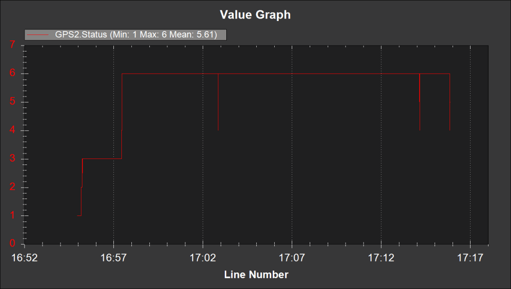
I made some setting changes to the RTK GNSS modules based on some great comments I received a few posts back. I outlined those changes in this post. After that post, I made one additional change to the CFG-NAVSPG-DYNMODEL configuration item. I set it to 3 = Pedestrian.
The graph above shows the RTK fix status. The changes I made in that post resulted in a rock solid RTK fix. The little dips in RTK status were less than a second in duration. Thank you to Sean Smith and Frank Beesly for their valuable feedback!
The magnetometer performance was more or less garbage. I think a good portion of my cross track error is due to the compass variance corrupting an otherwise good position solution given by my wheel encoders and RTK GNSS.
Reviewing the telemetry logs, before I was even in autonomous mode, the EKF was reporting a marginal compass health reading. And the chart below tells you all you need to know about the rest of the compass performance.

The reported magnetic field strength jumps by 0.15 Gauss after you turn the deck motors on. It might be possible to zero this out in the software by finding the offsets when the deck motors are on, but I have so little confidence in the magnetometer at this point, it’s not worth the effort in my opinion. RTK GNSS yaw seems like a much more robust solution for heading.
Keen observers will notice something peculiar at the 17:16 mark on these graphs. More on that in the next post.

Hi Mr Mower!
Interesting post, but I am very surprised by your power consumption for the cutting blades, that I find very high. I also engineered and built my own mower, and it needs much less power to do the job. It also has 3 motors in line to cut the grass on 80cm wide, and the speed is half yours (I measured 0.5 m/s with my RTK). But I only use a 16V 20Ah LI-ion battery to work 2 to 3 hours (depending on grass height). It is built to cut my garden’s grass in one pass. My mower by itself is light (10 kg, half for the motors), but I had to add weight to avoid spinning (4 to 8 kg depending on the tyres width, because I have 2 different prototypes).
Yesterday I measured current needed for rotating blades without cutting anything: 0.75 A per motor for 16V (so around 3000 rpm), 1.0A with 20V and 1.3A with 24V! So I will probably move to 24V in the future and go faster…
I use small blades mounted on disks to reduce air rubbing, and the disks are tilted to be lower in front of the mower, so that the grass already cut can’t touch the disk or blades anymore, in order to reduce frictions and power consumption…
When cutting grass, each motor uses a few amps (2 to 4 typically), depending on grass density. But I reduce the mower speed by half when motors use more than 4A (not often). Whatever the difference in consumption stays huge, even if your mower is larger and faster! So are you sure that you don’t waste a lot of power in frictions or anything else like that?
Sorry for my english but I am french…
Pierre
LikeLike