Previously I was using GPS blending between a u-Blox NEO-M8N and a ZED-F9P. When the F9P had an RTK fix solution, all was well. But after losing the RTK fix, the position estimate reverted to the inferior M8N position solution.
So I conducted a few experiments to see if there was a way to get a better position estimate. I realized while tweaking parameters that the final position estimate is what we’re really trying to improve, not just the quality of our RTK fix from the F9P module. A better RTK fix will help our position estimate, but that’s only part of the equation.
Instead of feeding arbitrary coordinates into the base F9P module, this time I let it survey in with a precision of 2.5m and a time of 300s. I was surprised how close to the map imagery the survey in solution was. It was off by ~18in would be my guess.
I started by unplugging the M8N module, but unfortunately the compass is also powered by the 5V and GND pins on the data cable. So with both modules active, I set the GPS_AUTO_SWITCH parameter to 3, so that only the second GPS, the F9P, would be used.
This was a great way to test things because the flight controller was still logging the M8N data, but it wasn’t used for computing the robot’s position.
I was skeptical that this change would actually improve things because the F9P maintains an RTK fix only intermittently at best. But the results surprised me.
The Ardupilot software has some magic in it (meaning code I don’t currently understand) that allows the rover to continue with high accuracy even without a GPS solution at times. I think the wheel encoders are helping significantly in this regard but I can’t say for certain.
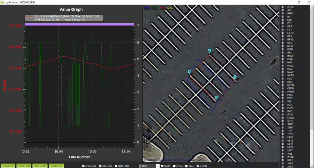
And related, the blue line is the M8N position accuracy. It’s really terrible. At times it’s a parking stall width, about 2m, from the RTK fix position. In hindsight, I was corrupting a really good position solution by blending it with a solution that was always off by at least 2m.
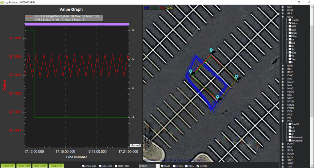
I looped the same square mission about 20 times and placed screwdrivers on the asphalt at the center of the robot’s travel to mark it’s path and check its repeatability. I would estimate the path drifted ~4in over the 20 loops.
Here’s a picture of the first few loops of the mission. Even with some hiccups in the RTK fix solution, the overall position estimate is very good.

I didn’t realize it until I started reviewing the logs, but the cell phone battery pack that I was using to power the base F9P module went to sleep after about 10 loops. That means no RTCM stream from the base, which means no RTK fix at the rover. But even without an RTK fix for 10 loops, the position solution was still very good.
In hindsight, the repeatability could be even better than ~4in that I was seeing if we could have intermittently re-established an RTK fix during that time.
Moral of the story: don’t ruin a really good answer (RTK fix) by averaging it with a really bad answer (3D fix).

Something that is bugging me is why in an open parking lot with your fixed base in place and the rover are you losing RTK at all? In my testing in the same scenario I’m not seeing drop outs, the cases where I’ve experienced that is if the rover moves to far under a tree or to close to a house and my los is obscured. Given I have 2 F9P configured. What is causing you to lose the RTK fix in an area with unobscured sky?
LikeLike
That is a great question, Sean. I did some reading this evening and found an excellent discussion related to the old M8P modules where users were reporting issues on quad copters:
https://discuss.cubepilot.org/t/here-does-not-hold-rtk-fixed-status-reliably-help-please/1056
I’m pretty sure the default u-Blox parameters allow satellites at very low elevations and signals with low signal to noise ratios. I think if I tighten those up on the rover side it may improve the robustness of the fix.
Related, I haven’t installed a true ground plane under the antenna. I thought the metallic robot chassis would be sufficient, but the antenna is still four inches above the battery bay lid (sandwiched between a bunch of flight control and radio electronics). Another thing I should probably try is actually grounding the ground plane, or maybe the chassis itself.
Thanks for bringing this up, I was kind of thinking these results were “good enough” but you’ve convinced me they could be a lot better given the environment.
LikeLike
All of the above could be related. For fun I repeated your parking lot experiment near me. I ran a square route for 35 min and never lost the RTK fix. I think maximal drift was 3-5cm over the entire course. I let the base station zero in for quite some time before starting though. If I were running this in my own yard, the base station will be fixed in the yard permanently. Keep us all posted on this because I’m very curious about whether its your ground plan or the mixture of the two types of receivers that is the issue.
LikeLike
I like your discussion on the various parts of your project. I have recently been working with the M8 and the F9 kits. The F9 seems to work a whole lot better. The ground plane is important though so you don’t get signals bouncing off the ground back up to you (multi path). The closer you are to the ground (short height from earth to antenna) the bigger problem this is going to be. A very good ground plane is the roof of a car — it is farther away from the ground and if your antenna is in the center then very little chance for multi path. For your bot, I would try to double or triple the size of your plane and see if that helps. I don’t know if the M8 has it but the F9 has a setting for Dynamic Model. I changed this to Pedestrian or Stationary (consult manual for difference) as it will help filter the location as well. I have recently been playing with dual F9 (Ardusimple + Lite) to do location and heading and also connecting to an F9 base station over XBee-900 that is working quite well (Stationary Base, MB Base, MB Rover). Now starting to test with higher update rates.
LikeLike
Thanks for the comment Frank. Regarding the dynamic model, are you referring to the CFG-NAVSPG-DYNMODEL configuration item? The default appears to be 0 – PORT for portable, but somehow my actual setting is 8 – AIR4 for 4g acceleration. I don’t think I changed this setting, I wonder if Ardupilot set this parameter automatically. I had read that they were going to allow users to set the elevation mask within the Mission Planner software with a default value of 15°, even though the u-Blox default was 10°. Maybe they are setting some configuration items automatically without informing the user (not that most users would care or even notice).
Regarding ground planes, why would having your antenna closer to the ground make things worse? I am truly ignorant on this matter, just trying to learn. I would think the ideal situation would be the antenna on the ground, in which case there could be no multipath?
I have considered using two F9Ps for heading. What is the distance between your antennas? I think my robot is only large enough to get about 24in of spread between the antennas.
LikeLike
That is the correct config for dynamic model. If you are not doing lots of hard accelerations or aerial maneuvers, then the filters will probably work better to using one of the models closer to what a mower would be doing, like pedestrian.
My understanding on the ground plane is you could put it perfectly on the ground but that is not practical in most cases. Once you start raising it up you are going to get signals bouncing off of the ground along with direct input causing errors/ambiguity. To prevent this you need to create something that will block the signals (i.e. the sheet of metal). The antenna design will really dictate the minimum size of plane needed but the bigger the better at blocking extra signals. Since the angle for the multi path signals to hit your antenna changes with height, the higher off the ground then the harder it is for the multi path to hit the antenna. Also, look at the helix antennas and then you don’t have to have a ground plane. Pay attention to the antenna gain(dB or dBi).
My current test environment has the two antennas about 18 to 20 inches apart if I remember correctly. It seems to be working well at this point. If I understood the manual correctly the dynamic model you select can impact how well the heading works versus the antenna distance. I also have it set to 5 Hz update rate from the MB Base to MB Rover.
I am now looking to incorporate an ardupilot/rover device for mission planning. Which one are you using or would you recommend to a first timer?
LikeLike