Late last year I traded in the Honda for a small truck. As I was designing the robot lawn mower it quickly became apparent that it wouldn’t fit in my little sedan. And even if it could, I’m not sure how I would load and unload a machine that weighs 300lb by myself.
I thought about taking it apart to transport it and then putting it back together in the field. But that is a very inefficient way to do business. The Honda had a great run, it was 16 years old and needed a new timing belt so I figured it was time to upgrade.
I’m a big fan of goals. For my afternoon in the parking lot, here was my to do list:
- Figure out the best way to load and unload the robot mower into the truck.
- Install my new wheel encoders and make sure they are working robustly.
- Play with the RTK GPS modules.
- Take the robot into some tall grass and see how it performs.
I realized that I have a few more things I need to bring to the field with the new robot lawn mower, so I updated my checklist of things to bring or do prior to leaving the house:
- Cell phone with cellular data and enough storage space for several videos and photos
- AA batteries for the RC transmitter
- Make sure rover batteries are sufficiently charged
- The toolbox with hex wrenches, adjustable wrench, and screwdrivers
- Multimeter
- Laptop with a good battery charge
- Telemetry radio for the laptop
- SD card, installed in the Pixhawk
- RTK GPS receiver, antenna, and micro USB cable for power
- Rechargeable batteries for RTK GPS base station
- Prefetch any map data that will be needed in Mission Planner
- Preplan any missions that may be needed and save the waypoint files
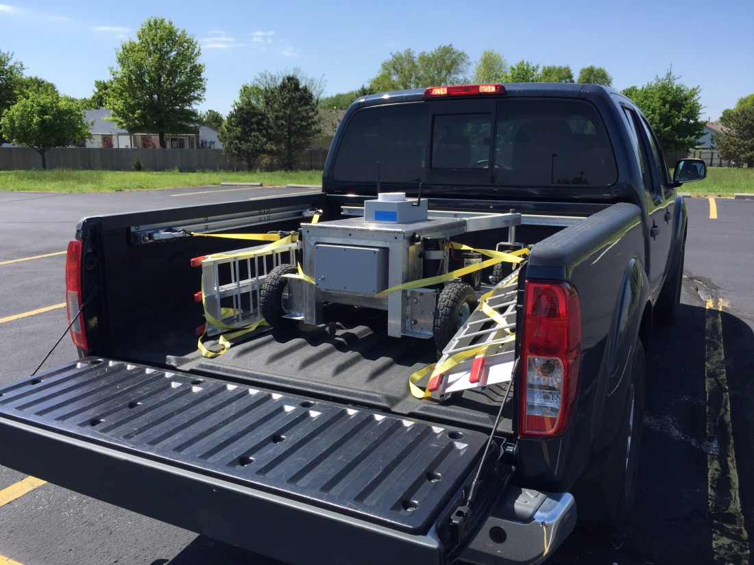
I typically would have gone to an actual field, but a parking lot offers some really nice geostationary markers that show up on satellite imagery: parking stripes.

My neighbor saw me using chunks of plywood to load the robot in the truck. He had some tailgate ramps he wasn’t using and let me borrow them for the day. I think I’m going to make him an offer for them. They were tremendously easy to use and transport.
The roof of a car makes for an awesome ground plane, so I decided to set up the RTK GPS base station on top of the truck. I noted which parking stall I was in and then found that same stall on the map imagery in Mission Planner and fed those coordinates to the ZED-F9P module.
To get a feel for how the RTK GPS was performing, I ran a circle mission.

On the map, the green line is GPS2, the position solution from the ZED-F9P module on the rover. The blue line is GPS1, the NEO-M8N module. My understanding is the red line is the EKF’s estimation of position after fusing sensor data with the GPS data.
The blue line is offset from the green line, even though their paths are pretty similar. I think this is because I arbitrarily selected the location of the base module. Essentially, I’m using two different origins: one for the RTK GPS versus whatever the M8N uses. This poses a problem when you lose the RTK fix.

The ZED-F9P module doesn’t lose the RTK fix gracefully. It frequently goes from RTK fix to no solution. After a few seconds though it usually returns to an RTK fix. But once it’s lost, the EKF replaces the F9P position solution with the M8N’s solution. Which is off by a few feet.
You can see an example of this behavior in the picture above. The position is heavily weighted to the F9P solution, but once it’s lost, it jumps immediately to the M8N solution. Interestingly, when the F9P reports an intermediate solution such as 3D fix, the weighting behavior is more of an average between the two receivers.
I double checked my parameters and GPS_AUTO_SWITCH = 2, so the EKF should be blending solutions, not just using the most accurate solution of the two. And when both receivers are in 3D fix mode, that’s the behavior you see.
I have some questions based on these observations:
- Is GPS blending really that useful? Maybe I should just ditch the M8N module all together. Whenever you have an RTK fix, it seems like this solution is so superior that the EKF basically ignores the M8N solution.
- For GPS blending, would an additional RTK GPS help? The reported accuracies from two identical modules would be similar. Maybe the redundancy would help when an RTK fix is lost on one receiver.
- Why does the EFK assume the robot’s position suddenly jumps? This is a rover, not a quadcopter. Especially when you have wheel encoders and an IMU, you should be able to assume that the robot’s position isn’t drifting significantly due to external disturbances, even if the GPS position jumps.
- If we could eliminate the offset between the two solutions by using the same “datums” would that make the failover more graceful?
Some of those questions can be turned into experiments I can conduct the next time I’m out in the field:
- Disable the NEO-M8N module. How does the robot respond when the ZED-F9P module loses an RTK fix?
- Instead of arbitrarily setting the coordinates of the RTK base module, we can let it “survey in” to determine its location. This may eliminate some of the offset between the F9P and M8N position solutions.
- We can measure the offset between the F9P and M8N solutions and then adjust the coordinates of the RTK base module to compensate. This would minimize the position jump between solutions when RTK fix is lost.
I also took the robot out into some taller grass to see how it would perform. You can see a video of it here. I also took a time-lapse of a typical grid run. Overall not bad, but for striping grass, it’s not good enough.
Going forward it looks like I will need ways to obtain a better position solution. I don’t think RTK GPS will get us there entirely. There are some exciting visual odometry solutions out there I may look into.
