Several comments on my post about the RTK GNSS results I experienced in the parking lot have made me reconsider how good my RTK fix really was. I was able to get a fix pretty easily, but it was fragile, and would frequently drop back to float without any apparent change in the environment.
When searching for ways to improve the robustness of the RTK fix, I came across this very comprehensive discussion about u-Blox receiver settings. The consensus I gathered from the discussion was that there are two configuration changes on the ZED-F9P boards that can really improve your RTK fix robustness: tightening up the elevation mask and increasing the signal to noise threshold.
To change these settings, I connected the ZED-F9P module via USB to my computer and then connected to it within the u-Center software. I then went to View > Generation 9 Configuration View. I double clicked on the Advanced Configuration on the left pane to show all the various configuration items.
You can use the CFG-NAVSPG-INFIL_MINELEV configuration item to set the elevation mask. This angle is measured from the horizon upwards. Satellites below this elevation are excluded from the navigation solution. The default is 10°, which I changed to 15°.
You can use the CFG-NAVSPG-INFIL_MINCNO configuration item to set the signal to noise ratio. The default is 6dbHz. I set mine to 35dbHz.
It was kind of a pain to remove the module from the robot, connect it to my laptop, change the settings, and then replace it in the robot, so I didn’t do any A-B testing on these values, although I may in the future. The 15° elevation mask and 35dbHz signal to noise values were recommended from the discussion linked to above.
I did do an A-B test on an aluminum foil ground plane to see how that would improve the fix quality.
An aluminum foil ground plane underneath the RTK GNSS antenna.
Below is the results with and without the ground plane. Initially I had the robot parked in my driveway under some trees, but after waiting more than 10 minutes for an RTK fix, I decided to drive the robot out in the street where there was a better view of the sky. Shortly thereafter, I got a fix.
The RTK GNSS performance without a foil ground plane. Left vertical axis is fix status where 6 = RTK fixed, and right vertical axis is the number of satellites seen by the receiver.
But with the foil ground plane, I was actually able to get a fix in my driveway under the trees. I drove the robot along my street at about 2:30 to see how robust the fix was. Much fewer hiccups, even with a more challenging environment.
The RTK GNSS receiver performance with a foil ground plane.
I ran the same mission down my street and back with and without the foil ground plane. The ability to keep the RTK fix with the foil was quite surprising. It’s definitely an improvement.
I will take these settings and foil ground plane to the parking lot soon and see how they perform.
Previously I was using GPS blending between a u-Blox NEO-M8N and a ZED-F9P. When the F9P had an RTK fix solution, all was well. But after losing the RTK fix, the position estimate reverted to the inferior M8N position solution.
So I conducted a few experiments to see if there was a way to get a better position estimate. I realized while tweaking parameters that the final position estimate is what we’re really trying to improve, not just the quality of our RTK fix from the F9P module. A better RTK fix will help our position estimate, but that’s only part of the equation.
Instead of feeding arbitrary coordinates into the base F9P module, this time I let it survey in with a precision of 2.5m and a time of 300s. I was surprised how close to the map imagery the survey in solution was. It was off by ~18in would be my guess.
I started by unplugging the M8N module, but unfortunately the compass is also powered by the 5V and GND pins on the data cable. So with both modules active, I set the GPS_AUTO_SWITCH parameter to 3, so that only the second GPS, the F9P, would be used.
This was a great way to test things because the flight controller was still logging the M8N data, but it wasn’t used for computing the robot’s position.
I was skeptical that this change would actually improve things because the F9P maintains an RTK fix only intermittently at best. But the results surprised me.
An excellent position estimate even with spotty RTK fixes.
The Ardupilot software has some magic in it (meaning code I don’t currently understand) that allows the rover to continue with high accuracy even without a GPS solution at times. I think the wheel encoders are helping significantly in this regard but I can’t say for certain.
And related, the blue line is the M8N position accuracy. It’s really terrible. At times it’s a parking stall width, about 2m, from the RTK fix position. In hindsight, I was corrupting a really good position solution by blending it with a solution that was always off by at least 2m.
I looped the same square mission about 20 times and placed screwdrivers on the asphalt at the center of the robot’s travel to mark it’s path and check its repeatability. I would estimate the path drifted ~4in over the 20 loops.
Here’s a picture of the first few loops of the mission. Even with some hiccups in the RTK fix solution, the overall position estimate is very good.
Several loops of the square mission. Even with some bad position data from the ZED-F9P module (green track) the position estimate (red track) is still rock solid.
I didn’t realize it until I started reviewing the logs, but the cell phone battery pack that I was using to power the base F9P module went to sleep after about 10 loops. That means no RTCM stream from the base, which means no RTK fix at the rover. But even without an RTK fix for 10 loops, the position solution was still very good.
The position solution with only a 3D Fix from the ZED-F9P. The red track is still solid.
In hindsight, the repeatability could be even better than ~4in that I was seeing if we could have intermittently re-established an RTK fix during that time.
Moral of the story: don’t ruin a really good answer (RTK fix) by averaging it with a really bad answer (3D fix).
Transporting the robot lawn mower. With the lead acid batteries installed, it weighs close to 300lb.
Late last year I traded in the Honda for a small truck. As I was designing the robot lawn mower it quickly became apparent that it wouldn’t fit in my little sedan. And even if it could, I’m not sure how I would load and unload a machine that weighs 300lb by myself.
I thought about taking it apart to transport it and then putting it back together in the field. But that is a very inefficient way to do business. The Honda had a great run, it was 16 years old and needed a new timing belt so I figured it was time to upgrade.
I’m a big fan of goals. For my afternoon in the parking lot, here was my to do list:
Figure out the best way to load and unload the robot mower into the truck.
Install my new wheel encoders and make sure they are working robustly.
Play with the RTK GPS modules.
Take the robot into some tall grass and see how it performs.
I realized that I have a few more things I need to bring to the field with the new robot lawn mower, so I updated my checklist of things to bring or do prior to leaving the house:
Cell phone with cellular data and enough storage space for several videos and photos
AA batteries for the RC transmitter
Make sure rover batteries are sufficiently charged
The toolbox with hex wrenches, adjustable wrench, and screwdrivers
Multimeter
Laptop with a good battery charge
Telemetry radio for the laptop
SD card, installed in the Pixhawk
RTK GPS receiver, antenna, and micro USB cable for power
Rechargeable batteries for RTK GPS base station
Prefetch any map data that will be needed in Mission Planner
Preplan any missions that may be needed and save the waypoint files
I typically would have gone to an actual field, but a parking lot offers some really nice geostationary markers that show up on satellite imagery: parking stripes.
The parking lot. Wide open skies, flat pavement, and geostationary lines. A perfect laboratory for implementing the RTK GPS modules.
My neighbor saw me using chunks of plywood to load the robot in the truck. He had some tailgate ramps he wasn’t using and let me borrow them for the day. I think I’m going to make him an offer for them. They were tremendously easy to use and transport.
The roof of a car makes for an awesome ground plane, so I decided to set up the RTK GPS base station on top of the truck. I noted which parking stall I was in and then found that same stall on the map imagery in Mission Planner and fed those coordinates to the ZED-F9P module.
To get a feel for how the RTK GPS was performing, I ran a circle mission.
A circle mission in the parking lot with RTK GPS.
On the map, the green line is GPS2, the position solution from the ZED-F9P module on the rover. The blue line is GPS1, the NEO-M8N module. My understanding is the red line is the EKF’s estimation of position after fusing sensor data with the GPS data.
The blue line is offset from the green line, even though their paths are pretty similar. I think this is because I arbitrarily selected the location of the base module. Essentially, I’m using two different origins: one for the RTK GPS versus whatever the M8N uses. This poses a problem when you lose the RTK fix.
An example of how the position solution from the EKF jumps when RTK fix is lost.
The ZED-F9P module doesn’t lose the RTK fix gracefully. It frequently goes from RTK fix to no solution. After a few seconds though it usually returns to an RTK fix. But once it’s lost, the EKF replaces the F9P position solution with the M8N’s solution. Which is off by a few feet.
You can see an example of this behavior in the picture above. The position is heavily weighted to the F9P solution, but once it’s lost, it jumps immediately to the M8N solution. Interestingly, when the F9P reports an intermediate solution such as 3D fix, the weighting behavior is more of an average between the two receivers.
I double checked my parameters and GPS_AUTO_SWITCH = 2, so the EKF should be blending solutions, not just using the most accurate solution of the two. And when both receivers are in 3D fix mode, that’s the behavior you see.
I have some questions based on these observations:
Is GPS blending really that useful? Maybe I should just ditch the M8N module all together. Whenever you have an RTK fix, it seems like this solution is so superior that the EKF basically ignores the M8N solution.
For GPS blending, would an additional RTK GPS help? The reported accuracies from two identical modules would be similar. Maybe the redundancy would help when an RTK fix is lost on one receiver.
Why does the EFK assume the robot’s position suddenly jumps? This is a rover, not a quadcopter. Especially when you have wheel encoders and an IMU, you should be able to assume that the robot’s position isn’t drifting significantly due to external disturbances, even if the GPS position jumps.
If we could eliminate the offset between the two solutions by using the same “datums” would that make the failover more graceful?
Some of those questions can be turned into experiments I can conduct the next time I’m out in the field:
Disable the NEO-M8N module. How does the robot respond when the ZED-F9P module loses an RTK fix?
Instead of arbitrarily setting the coordinates of the RTK base module, we can let it “survey in” to determine its location. This may eliminate some of the offset between the F9P and M8N position solutions.
We can measure the offset between the F9P and M8N solutions and then adjust the coordinates of the RTK base module to compensate. This would minimize the position jump between solutions when RTK fix is lost.
I also took the robot out into some taller grass to see how it would perform. You can see a video of it here. I also took a time-lapse of a typical grid run. Overall not bad, but for striping grass, it’s not good enough.
Going forward it looks like I will need ways to obtain a better position solution. I don’t think RTK GPS will get us there entirely. There are some exciting visual odometry solutions out there I may look into.
I updated the firmware for my SimpleRTK boards this evening. Below are my notes for the process in case I need to do it again. There was some obscure information I had to hunt down to get things working right, and I’m linking to it here so it will be available in the future after I’ve forgotten.
Download the latest firmware from the u-Blox website. As of this writing, HPG112 appears to be the latest and greatest. Save it to your computer to a place you can get to it.
Open up u-Center, u-Blox’s GNSS evaluation software.
Connect the GNSS module you want to update to your computer via USB cable. Connect to the appropriate COM port within the u-Center software by going to Receiver > Connect.
Within u-Center, go to Tools > Firmware Update. Navigate to the location of the firmware .bin file and check the boxes as shown below.
The settings I used at the advice of the ArduSimple website.
In the lower left of the Firmware Update Utility window, there should be a green Go button. Click it to update the module.
Repeat this process for the second ZED-F9P module.
I reset the configuration files for both modules to the default provided by ArduSimple. You can find those configuration files on their GitHub page. Download both and save them to a location you can get to. I have the LR xBee radios, so I used their srtk2b_rover_FW_HPG112.txt and srtk2b_base_FW_HPG112.txt files.
To upload a configuration file, go to Tools > Receiver Configuration.
Before you upload the configuration files, it’s not a bad idea to back up the existing ones. Use the Transfer GNSS > File button to create a backup.
To upload a new configuration file, select the appropriate configuration file for either the base or rover module you’re connected to and use the Transfer File > GNSS button.
The Receiver Configuration window. Save a back up of your existing configuration, just in case!
I got a warning that said the firmware version of the module didn’t match the configuration file. I took a gamble and ignored this message. Things turned out okay, as of this writing.
Repeat this process for the second module.
Unfortunately, after updating the firmware and the configuration files, the xBee radios weren’t working. I found this thread on the ArduSimple website to be helpful. Basically, after you upload a configuration file, you have to save the configuration. It doesn’t do so automatically.
To save the configuration, you need to go View > Configuration View, and then click on the CFG option in the left panel on the screen.
There should be a radio button labeled Save Curent Configuration. If it’s not selected, select it. Then click Send in the lower left of the window. This will send a save command to the module.
Take the modules outside and test them. I connected both to my laptop so I can toggle between the two in u-Center to make sure the base module reports TIME and the rover module reports 3D/GNSS/FIXED in the black window that has the latitude, longitude, and altitude shown.
If you don’t see TIME on the base, you’re not sending RTCM correction messages to the rover. On the ArduSimple modules, the GPS > XBEE or XBEE > GPS LEDs should blink on both modules if the base reports TIME.
To make sure corrections are being broadcast form the base and received by the rover, I went to View > Messages View and then click UBX > NAV > RELPOSNED. There should be a length in that window that should roughly match the distance between the antennas.
I also discovered that in order to set the survey in or fixed location of the base, you need to go to View > Generation 9 Configuration View and then select the Advanced Configuration option on the left of the screen. Under the CFG-TMODE option you can set the base behavior.
If you want to set fixed coordinates for the base you need to change CFG-TMODE-MODE to E1 – 2 – FIXED and then plug in either the north, east, down (NED) or latitude, longitude, and height (LLH) values for the base location. u-Center requires you do provide it with LLH in 1e-7 degrees, so 12.3456789° is 123456789 in the value field.
Drawing pictures in a CAD program is fun, but when the rubber meets the road and you start fabricating something, you quickly notice some areas that weren’t too well thought out. Lately I’ve been backfilling those issues as we discover them at the shop. Here are some things I’ve tweaked over the past few weeks. Hopefully we’ll have a finished robot lawn mower soon!
Mower Deck to Chassis Interface
When the deck is stationary in my CAD program, chains look like a great way to support it. I can flip the model upside down and they don’t even move! But when the robot lawn mower starts rolling in reality, what keeps the deck from swaying all over the place? Well, if it hangs from chains, the answer is nothing.
The turnbuckle that will replace the chain used to attach the mower deck to the chassis.
Unfortunately, the chassis weldment and the mower deck weldments are pretty much complete. So whatever fix we come up with has to interface with those features like the chain did. The solution? Turnbuckles! Some really small turnbuckles, to be exact.
The eye on these little guys is 0.26in ID, perfect for the 1/4-20 screw I had planned on using. The length is adjustable from 3.375in to 4.625in long. They’re rated for 36lb, a strangely specific number, but with three of them they should work fine. The mower deck weighs just over 30lb.
Steel Mower Blades
Another issue the shop made me aware of was the mower blades. I don’t remember if I mentioned it or not, but the reason I designed the robot lawn mower out of aluminum was to avoid any compass interference issues. You may recall I ditched the compass a few months ago, but I never went back and changed the design to steel.
The shop thought that aluminum mower blades were a goofy idea. They’re not wrong, but at least I had a reason for making them that way. Kenny Trussell discovered that when the blades spool up to speed, they interact with the earth’s magnetic field in a way that skews your apparent compass heading.
Making them out of aluminum would avoid that issue, as they’d be non-ferrous. But since we’re not using the compass anymore, it seemed like a reasonable change to make. Besides, all the mower blades you see out in the wild are made from steel.
And if there’s one thing I’ve learned working with fabrication guys, if they make a suggestion that doesn’t impact your design significantly and doesn’t cost much, change it. It’s an easy way to show them you value their input, and they’ll do whatever it takes to get your design working now that their finger prints are on not just the physical parts, but the design, too.
A Legit GNSS Antenna Enclosure
On the wheelchair robot, I had the two GNSS modules velcroed to the top of the robot. That doesn’t seem befitting of a robot I’ve spent a year and a few thousand dollars making. So I designed a small 3D printed enclosure for the RTK GNSS antenna and the UBlox M8N module. It sits on top of a small ground plane disk, mounting to the lid of the electronics enclosure.
A 3D printed GNSS antenna enclosure. The larger GNSS antenna is for the Ardusimple RTK GNSS module. The smaller one is a UBlox M8N.
Everybody I talk to says you need a really good ground plane for your antennas. That’s what the circular disk is below the enclosure. The screws for the lid of the enclosure are plastic. Hopefully this doesn’t create any reception issues. I also hope that the antennas don’t have to be perfectly concentric with the ground plane. If anybody has experience with ground planes, I’ll take any advice or feedback you can give me!
Mower Deck Discharge Chute
For some reason I had it on the left side of the mower deck. The shop mentioned that most mowers have the discharge chute on the right side of the deck. I don’t want people latching on to minor quirks of my design, so changing it to the right side seemed like a good idea.
Mower Deck Progress
Here’s the progress on the mower deck last time I visited the shop. We’re a few roll formed parts short of a robot lawn mower!
The mower deck weldment just before Christmas, 2019.
My favorite Mission Planner error message: Bad Compass Health.
The compass drives two very costly design constraints into the robot lawn mower:
The need to minimize the number and size of steel or ferrous parts in the design.
The need to separate the compass from the motors to prevent electro-magnetic interference.
To address the first constraint, I selected a 5000 or 6000 series aluminum for the robot chassis and deck. That is quite costly both from a material standpoint and from a fabrication standpoint. And ultimately, you’re going to have some amount of steel in your robot. You can’t avoid it.
The second constraint requires the compass to be raised above the motors to a level high enough to get it out of the magnetic field created by the motors. Because I’ve placed the flight controller and other electronics in the same control box with the compass, several wires have to be run between this box and the power box. Shielding those wires is going to be tricky. Long story short, it creates lots of secondary design inefficiencies.
Reading through the forums and in my own research, I’ve come across a few interesting anecdotes:
Kenny Trussell reports that when steel mower blades begin to spin at high RPMs, the compass heading begins to drift by some amount, about 20º.
Christopher Milner had to place a 4ft tall mast on his vehicle to sufficiently separate his compass from the noise created by two drive motors and one brushless DC motor.
Unplugging and disabling all compasses on my wheelchair robot doesn’t cause any EKF errors, and after traveling a few feet in the wrong direction, the robot corrects its heading somehow, without the compass. I suspect the wheel encoders aid this process.
In light of this information, I am beginning to question whether I even need a compass. It seems to be creating more problems that it solves. The bad compass health error messages in Mission Planner are starting to get very annoying, even though they don’t usually seem to impact the robot wheelchair’s ability to navigate properly.
According to U-Blox, you can use two ZED-F9P modules configured as a moving base-rover combination to calculate the vehicle’s heading. Even with a spread between the antennas of 10in, U-Blox says the heading accuracy is 0.8º. Some folks on the Ardupilot forum are starting to investigate using the modules in this way, and I suspect it will be a much more accurate way to obtain the vehicle’s heading.
I’ve had enough bad luck with compasses that I’m willing to get rid of them altogether and use the ZED-F9Ps for heading exclusively. This allows some significant improvements to the robot design. I guess I’ll head back to the drawing board for the time being…
I may not be able to afford a Emlid Reach RS2, but I’ve got a cordless drill and an Amazon Prime account, dang it!
Putting my RTK base station on the mailbox works pretty good, but it takes a while to set it up and it’s not very robust. Using it in this manner results in a few problems:
The cell phone battery pack that I use to power to the receiver turns off after a while. I’m not sure if this is because the receiver only draws ~120mA of current and it doesn’t detect the receiver, or if it just times out. Either way, it’s quite annoying to discover the reason I can’t get an RTK fix or float is because the base station isn’t even on.
The neighbors getting their mail usually block enough satellite signals to cause the receiver to lose an RTK fix. Cars driving down the street will often affect the quality of reception, too. Unfortunately, I can’t pick up the mailbox and move it to a more favorable location.
The receiver and antenna are exposed to the elements. While I usually use them in good weather, I would like to be able to use them without having to worry about risking damage to the units from rain, wind, and the Kansas critters.
When I’m out testing in the parking lot there’s not an equivalent of my mailbox out there for me to set the receiver on. The roof of my car doesn’t count because it’s not geostationary. I’d like to have a way to repeatably locate the receiver when I’m testing in the parking lot.
Maybe I’m paranoid, but I’m always worried about some punk kid walking off with the base station module when it’s not within my line of sight. The punk kid I used to be in my teenage years would have done something malicious like that. It’d be great if I could make it a little bit more difficult to steal.
With these goals in mind, I decided it was time to build a real base station. One like the Emlid Reach RS2, but doesn’t cost me $1,899.
A Glorified Enclosure
The Emlid guys are geniuses. They basically took an RTK GNSS chip they can buy in bulk for $150 a piece, slapped it in a super nice thermoplastic case, developed an app that is more or less equivalent to U-Blox’s U-Center, and then stuck a price tag of $1,899 on it. I’m embarrassed I didn’t think of doing it myself.
They do offer some nice benefits with that $1,899 price tag, such as integral Wi-Fi and data logging capability, but in my humble opinion, those features aren’t worth what they’re charging. Realistically, I need a tripod, a mostly waterproof enclosure, a lead acid battery with a charger, and a cover for my GNSS antenna. Something like this:
My version of the Emlid Reach RS2.
I have a 12V lead acid battery and charger I stole from an old weed eater that I intend to use for this enclosure. The battery is rated for 3.6Ah, and according to the Ardusimple website, the board consumes 600mW at 5V, so 120mA of current. That would mean you could keep the Ardusimple board on for 30 hours. Not too shabby! I don’t know if they’re including the radio current consumption in those numbers, but even if it’s twice the 600mW they listed, we should be in good shape.
I’m still learning how to use these GPS modules, so I want to have access to the micro USB port that lets me communicate with them via U-Center. I found one of these cables for that purpose. I want to be able to interface with the board without opening the enclosure.
The guys that designed the Ardusimple boards were very forward thinking, and they made them such that you can power the board from any port or all the ports. The board has two micro USB ports, one for GPS data and the other for debugging the XBee radios. I don’t anticipate needing to use the XBee port often, so I am going to power the board with it instead.
To step down the 12V to 5V the board needs, I am going to use one of these DC to DC buck converters. Instead of two wire leads for the 5V output, it has a micro USB connector. Very handy. This converter should plug and play right into the XBee micro USB port.
One concern I have with it is RF interference. I’ve read some comments saying these converters don’t play well with FM radios. The way my enclosure is designed, I’ve got it sitting right below the Ardusimple board. GPS signals are in the 1.5GHz range if I remember right, so maybe we’ll be okay.
I’d like to use a tripod that’s stouter than your consumer grade camera tripod. Ideally it would have a hook under the center that I can hang a plumb bob from to make sure I’m setting the tripod up in the same location every time. I found a tripod that appears to fit the bill on Amazon.
A survey grade tripod that looks promising. The 5/8-11 UNC stud is stout, but a little inconvenient.
Most survey grade tripods appear to have a 5/8-11 UNC threaded stud, so I’ve used a low profile cap screw with a coupling hex nut to mount the enclosure on the tripod.
The coupling nut used to interface the enclosure with the tripod.
Last but not least, I need a way to protect the antenna as it sits on top of the enclosure. I opted for the OEM antennas that Ardusimple sells for the simple reason that all the other antennas they offered came with no less than 5m of extra cable. Yikes. Where would you put all of that cable? The OEM antenna cable was 30cm long.
The downside to the OEM antenna is that it doesn’t have any protective case. I could have 3D printed something, but I like to keep things simple. I really just need a dome looking thingy to cover it.
It’s kind of amazing what Google can find if you type “plastic dome” into the search field. At least for me, it turned up this on the first page of results. Pretty much exactly what I’m looking for. I intend to use a modified pipe gasket and some rubber washers for an approximately water tight seal.
The dome is about an eighth of an inch thick, so to make sure it doesn’t attenuate the GPS signals too much, I did a little test where I put a similar plastic bowl over the receiver. It affects the signal strength only marginally.
Last but not least, every GPS antenna needs a good ground plane. Sparkfun sells a 4in diameter ground plane for $5. It’s 0.125in thick steel which is a bummer for drilling holes through, but it beats routing the circular profile out of a piece of bar stock.
Bill of material for the poor man’s RTK GPS base station. The items I have on hand have a zero quantity.
Total cost? Should be under $200, depending on shipping for all these items. You too can have a Emlid Reach RS2 for the low, low price of $200.
I have decided that I need to refine the wheelchair robot’s ability to navigate accurately and robustly before I shell out a few thousand dollars to build the robot lawn mower. The goal here is to have the wheelchair robot “mow” my lawn before I invest in the actual robot lawn mower. If the wheelchair robot can’t do it, the robot lawn mower doesn’t have much of a chance, either.
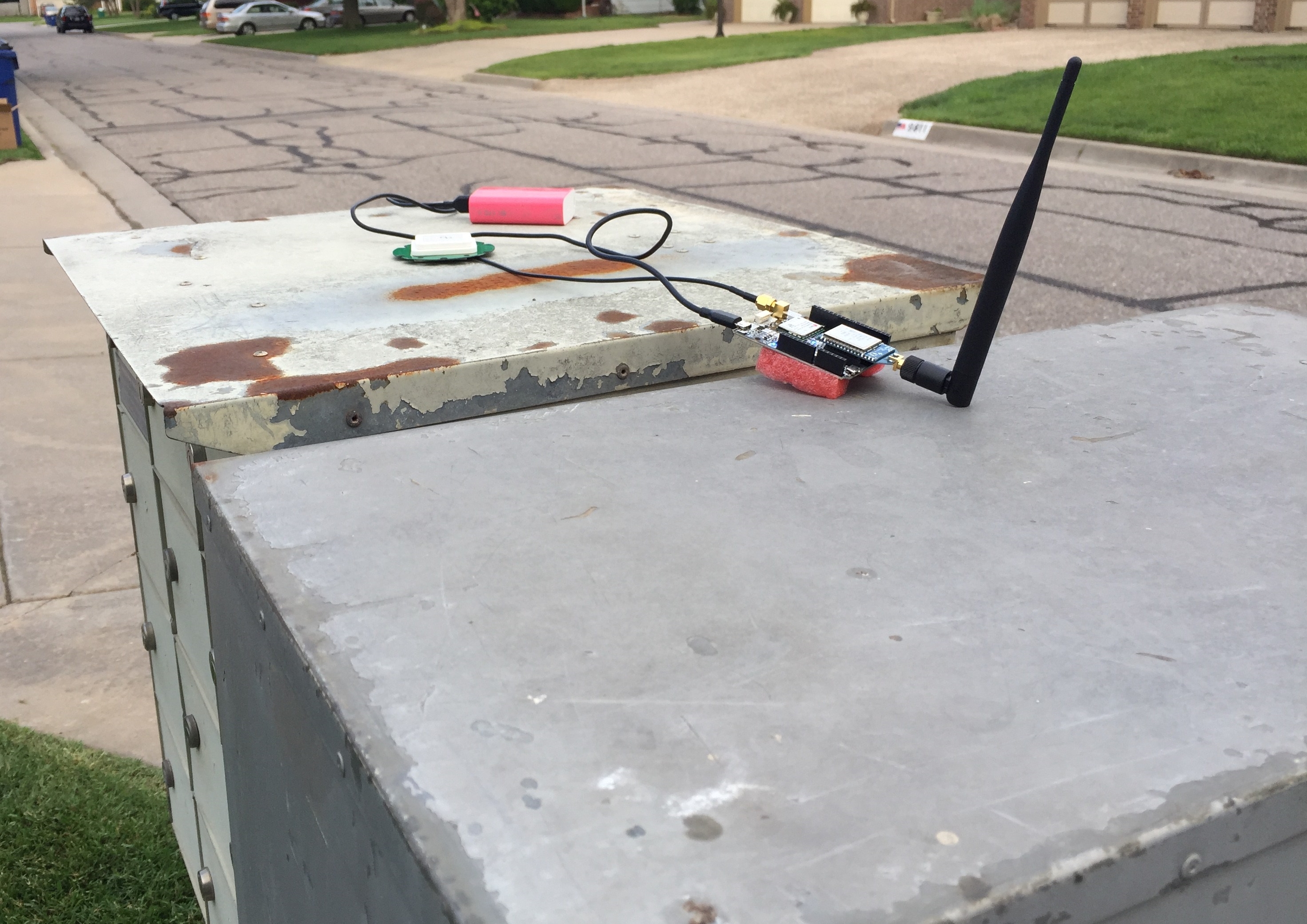
So I’ve spent most of my time testing the wheelchair robot and the RTK GPS system. I have been typically placing the base on my community mailbox because it is geostationary, has a large metallic surface to prevent multipath, and a decent view of the sky.
The base station, located on top of my community mailbox. The green disk is the antenna. Neighbors give me funny looks when they go to get their mail.
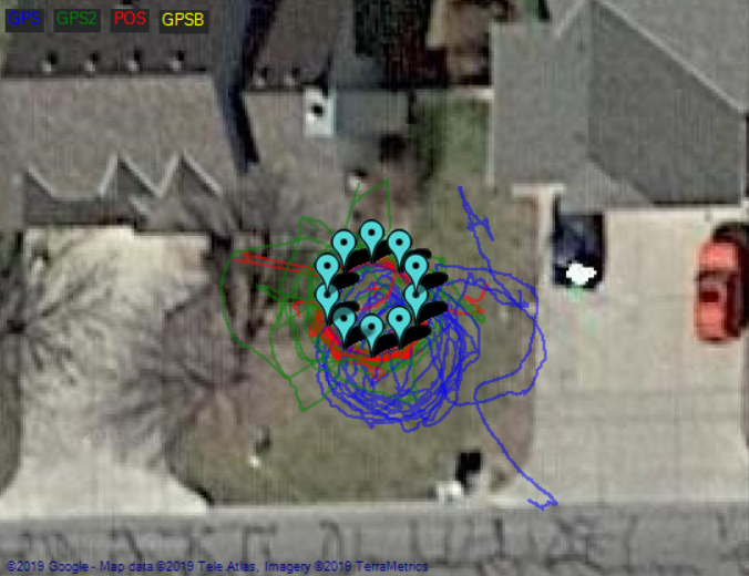
Surprisingly, I was able to get several RTK Fixes partially underneath my large maple tree in my front lawn. While in RTK Fixed mode I had the rover running a mission with 10 waypoints in a 3m diameter circle. I cranked down the waypoint radius to 0.3m to try and make sure the robot was accurately traveling to each waypoint.
The circular mission in my front lawn. The satellite imagery is from winter time. GPS in blue is the U-Blox Neo-M8N, GPS2 in green is the U-Blox Zed-F9P, and POS in red is the calculated position by the EKF.
The map above shows some calculated positions prior to obtaining the RTK fix and after the RTK fix is lost.
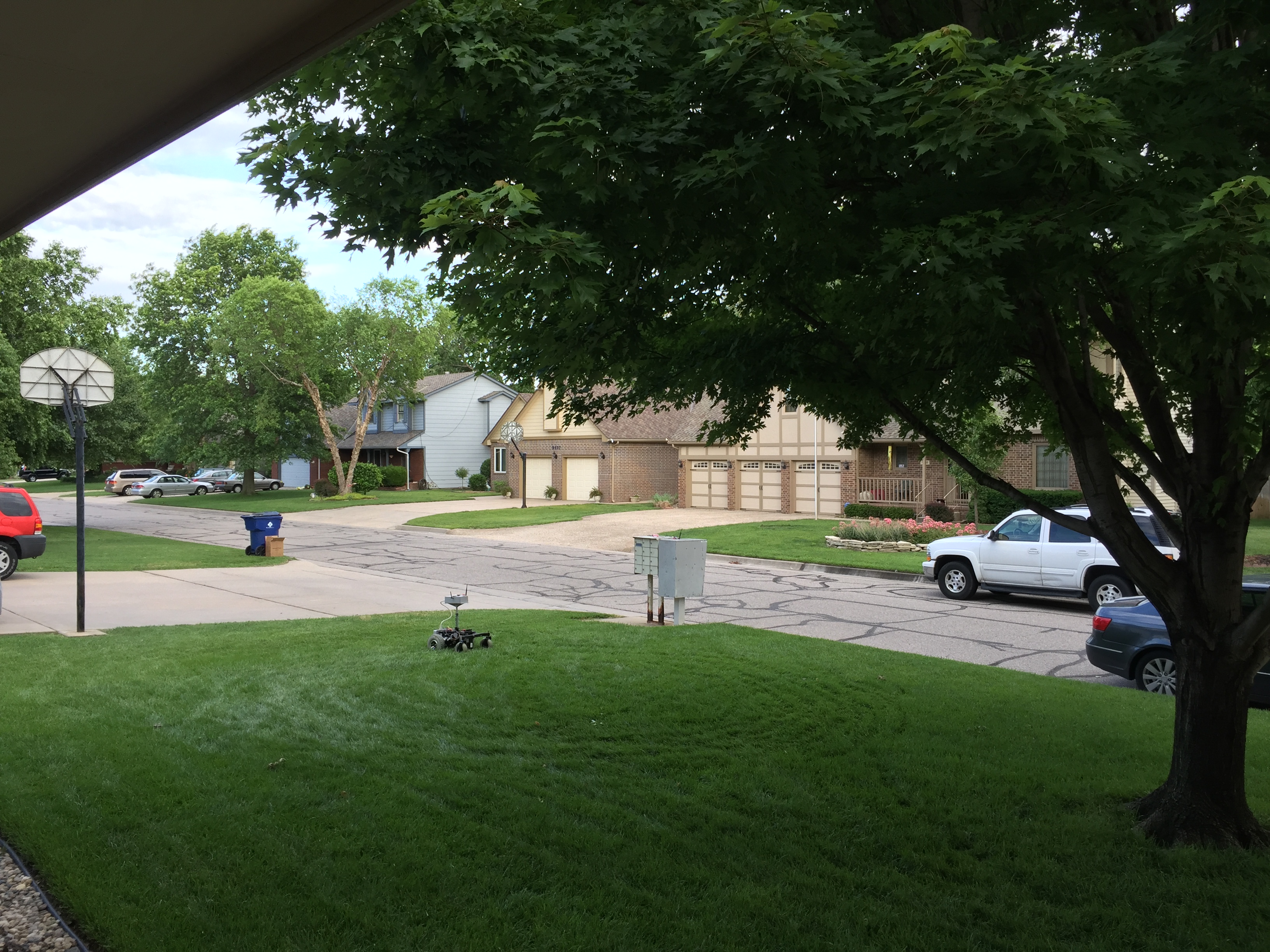
The view from the ground. The mailbox in the picture is where I have the base station sitting.
There is some offset between the satellite imagery and the actual location on the ground, which makes things a little confusing, especially when planning a mission close to many obstacles. I almost ran into my neighbor’s basketball goal after I lost my RTK fix.
To give you a better idea of the quality of the fix, here is the latitude reported by the GPS receivers and the blended location as calculated by the EKF:
The latitude reported by the U-Blox Neo-M8N, U-Blox Zed-F9P, and the EKF position estimate in blue, green, and red, respectively.
The RTK fix in the graph above is first obtained at 18:06:15 and is maintained intermittently until about 18:14:12. The reported HDOP for both GPS receivers was close to 0.7, but despite this, I am impressed that by default, the EKF is giving much more weight to the RTK solution. You can see this in the graph: the red and green lines are much closer than the blue line.
The oscillations in the graph above are from the circular mission I was running. It looks like I had a pretty good RTK fix from about 6:09PM to about 6:13PM. This was about 11 laps about the circle.
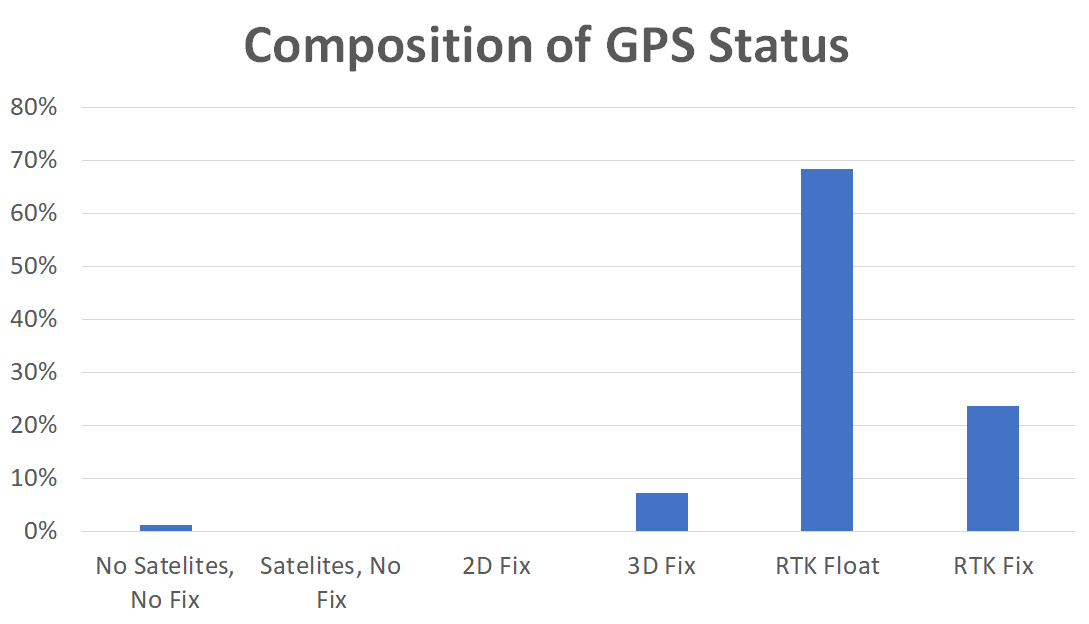
Some additional information about the fix status:
The fix status across time. 6 is an RTK Fix, 5 is RTK Float.
How much time was spent in each fix status.
I don’t want to oversell these results, because they weren’t typical of the entire afternoon. I spent a good chunk of time running the wheelchair robot in Acro mode tuning the throttle and steering parameters, and I wasn’t able to get an RTK fix throughout that time. It’s very much a patience thing.
The weather the past two weekends has been good enough to take the robot out for some testing with the new RTK GPS system. The Ardusimple boards are pretty awesome. The things I like about them:
It is plug and play with the Pixhawk (mostly).
It is configured to automatically survey in the base location. This means you don’t have to mess with U-Center and configure it out of the box, unless you want to plug in specific coordinates.
The long range radios I ordered mean you don’t have to mess with injecting the RTCM data stream through telemetry, although I will eventually attempt this.
Those things I like are huge. A few minor things I didn’t like:
The connector on the board is technically the correct Pixhawk connector, a JST-GH 6 pin connector. Which is great, but every Pixhawk I’ve seen has DF13 connectors. So I had to buy an adapter cable.
And then I had to mod the adapter cable because apparently the pinouts are inverted between the DF13 and JST-GH connectors. Frustrating.
The antenna choices offered by Ardusimple included a nice IP65 antenna and a unenclosed one. Initially I wanted the IP65 antenna, but then realized it came with a 5m (!) long cable. Where are you supposed to store 15ft of wire on a robot like this? So I went with the unenclosed version with a 10cm long cable.
The robot wheelchair with the RTK GNSS antenna mounted to the top enclosure. The second longer antenna is for RTCM corrections from the base station.
Once you tweak the adapter cable, you can plug it in to your Pixhawk and get RTK positioning in no time flat! Very awesome. No need to even tweak anything in mission planner. It will interpret RTK float and RTK fixed messages from the rover module.
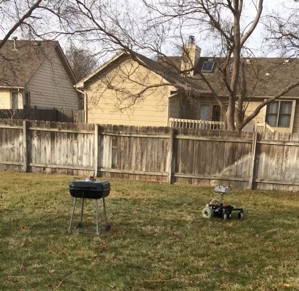
To set up a base station, I grabbed my charcoal grill, a micro USB DC adapter, and an extension cord.
The base station is on the grill. The thought was the metal shell would make a good ground plane to mitigate multipath.
And it worked pretty well until the rover tried to ram it in auto mode. Not cool, robot wheelchair. Not cool.
Another issue is that my backyard is a crappy GPS environment. It was pretty easy to get an RTK fix when stationary, but in motion losing one or two satellites was enough to bump back to RTK float. Bummer!
So to fix these two issues I moved the base station to my front yard which had a better view of the sky, and mounted the unit on the roof of my car, which I’ve heard makes an excellent ground plane. Whoever said that is right.
This was quite an improvement. I was able to run autonomous missions while maintaining an RTK fix for 80%+ of the time in the back yard.
The black tick marks is the position of the front caster as it runs a loop in my driveway.
I had the robot run an autonomous mission in circles in my driveway and the repeatability was still pretty good. The tick marks on the drive way indicate the position of the side of the front caster through each pass. The distance between the furthest two tick marks is 5in.
Overall, the Ardusimple boards are looking like a very good investment.