Several comments on my post about the RTK GNSS results I experienced in the parking lot have made me reconsider how good my RTK fix really was. I was able to get a fix pretty easily, but it was fragile, and would frequently drop back to float without any apparent change in the environment.
When searching for ways to improve the robustness of the RTK fix, I came across this very comprehensive discussion about u-Blox receiver settings. The consensus I gathered from the discussion was that there are two configuration changes on the ZED-F9P boards that can really improve your RTK fix robustness: tightening up the elevation mask and increasing the signal to noise threshold.
To change these settings, I connected the ZED-F9P module via USB to my computer and then connected to it within the u-Center software. I then went to View > Generation 9 Configuration View. I double clicked on the Advanced Configuration on the left pane to show all the various configuration items.
You can use the CFG-NAVSPG-INFIL_MINELEV configuration item to set the elevation mask. This angle is measured from the horizon upwards. Satellites below this elevation are excluded from the navigation solution. The default is 10°, which I changed to 15°.
You can use the CFG-NAVSPG-INFIL_MINCNO configuration item to set the signal to noise ratio. The default is 6dbHz. I set mine to 35dbHz.
It was kind of a pain to remove the module from the robot, connect it to my laptop, change the settings, and then replace it in the robot, so I didn’t do any A-B testing on these values, although I may in the future. The 15° elevation mask and 35dbHz signal to noise values were recommended from the discussion linked to above.
I did do an A-B test on an aluminum foil ground plane to see how that would improve the fix quality.

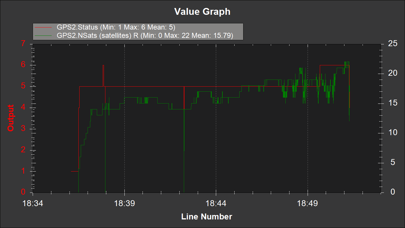
Below is the results with and without the ground plane. Initially I had the robot parked in my driveway under some trees, but after waiting more than 10 minutes for an RTK fix, I decided to drive the robot out in the street where there was a better view of the sky. Shortly thereafter, I got a fix.
But with the foil ground plane, I was actually able to get a fix in my driveway under the trees. I drove the robot along my street at about 2:30 to see how robust the fix was. Much fewer hiccups, even with a more challenging environment.

I ran the same mission down my street and back with and without the foil ground plane. The ability to keep the RTK fix with the foil was quite surprising. It’s definitely an improvement.
I will take these settings and foil ground plane to the parking lot soon and see how they perform.

Hi,
I recently stumbled across your amazing project. I had this idea for years but never thought an accurate GPS fix would ever be possible.
About the planning/navigation: How do you plan the mowing path?
I had the idea of an initial setup (for a residential use) where you can walk around with your robot the perimeter of the lawn and add exclusion areas (stone, water obstacles, …) that you also walk around.
And afterwards adapt the slicer software from 3D printers to plan the path up and down.
How did you implement this?
And another question. iRobot is going to release a residential robot next year.
How do you think their beacons work? I think they measure the mixture of electromagnetic fields emitted from the beacons to gain a position estimate. But I wonder if this can ever be precise enough with walls and obstacles resulting in multipath effects.
LikeLike
Hi Jacy,
As far as path planning goes, I am using the Ardupilot software on a Pixhawk flight controller in conjunction with Mission Planner. Mission planner allows you to set waypoints in a mission and upload it to the flight controller. Check out the Ardupilot.org website for more information.
Regarding the iRobot sensors, I wonder if they’re not acoustic beacons. I’ve seen systems where the beacons are synchronized with a radio and the emit a radio pulse at the same time as an ultrasonic ping, and by measuring the time delay between the radio pulse and the ultrasonic ping you can determine your distance to a beacon. Do that with three or more beacons and you can infer your location in 3D. I wonder how they’re powered, if they take batteries, better than burying a ground wire, but still a little bit of a hassle.
There are some exciting vision solutions coming online soon that will allow for some real obstacle avoidance and detection. Check out the Intel T265, for example.
I hope that answers your questions.
LikeLike