Featured

The Robot Mower in Action

The robot mower making its first autonomous stripes on a field.

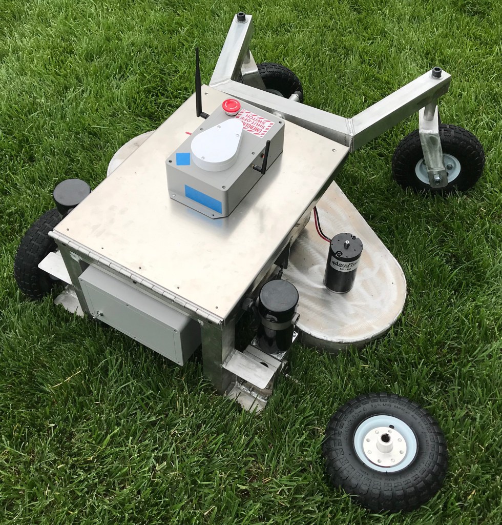
The past few Saturdays I’ve been playing with the robot mower in my backyard. It’s been fun manually driving it around my sprinkler well, flower beds, and garden. The fun ends a lot faster than I’d like: my push mower is 21in wide, but the robot mower is 36in wide, so it doesn’t take very many passes to get most of it mowed.

I’ve spent a lot of time in the backyard for two main reasons: firstly, I want to make sure the mower is safe before I take it somewhere it could hurt a bystander. And secondly, I want to make sure it doesn’t do an embarrassingly bad job at cutting grass.

Before I even took the mower out into the backyard, I ran it in my garage with the door down for a good hour or so to make sure the blades were installed securely. The first time I spooled it up was pretty scary. The garage is a giant echo chamber, and so it sounded a lot louder than when I had it running in the backyard.

Once I was satisfied it wasn’t going to vibrate apart, I maneuvered it into my backyard to see how it handled in manual mode, and how good of a job it did cutting my grass. Overall, it performed very well, making grass clippings without any difficulty. I did, however run into two issues:

The turnbuckle holding the deck to the chassis needs to be larger.

In manual mode, you can take turns pretty quickly, resulting in some large side forces on the turnbuckle eyes. These turnbuckles were only rated for 36lbf in tension and I wondered how well they’d hold up. Guess we know the answer to that question.

Locknuts are effective only if the locking portion of the nut is engaged with the threads.

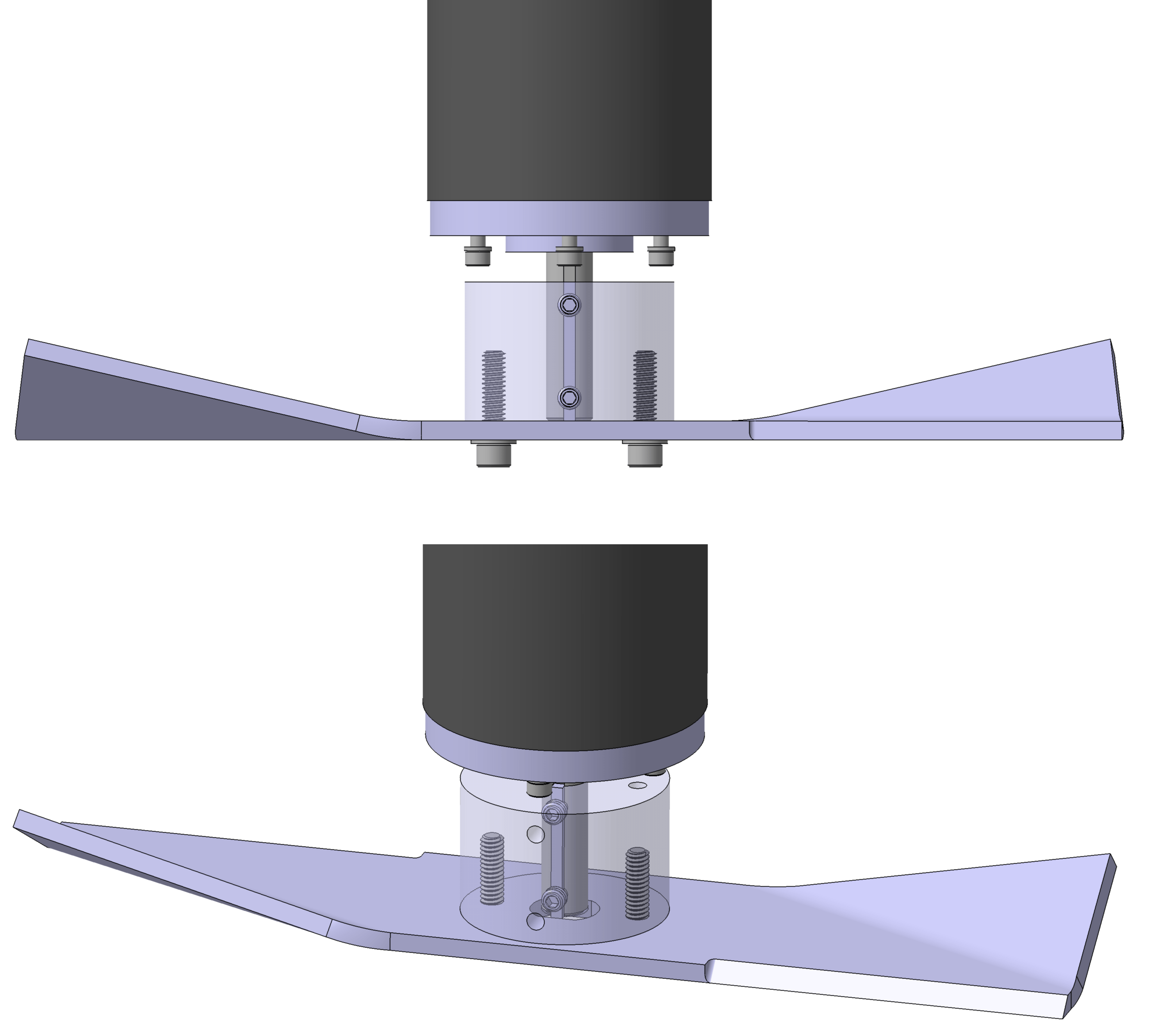
While taking one of those fast turns in manual mode, I had a tire pop off. Yikes! Upon closer inspection, it turns out the nylon portion of the locknuts on the motor shaft were not actually threaded onto the shaft.

In my CAD model I had 1.5 threads engaged. Not great, but enough engagement to where I wasn’t worried about it. In reality, I didn’t get them threaded on all the way. I replaced both locknuts with a split lock washer and a jam nut.

These were good issues to discover in the backyard, where I could easily fix them without much embarrassment.

The field. A great view of the sky and a few weeks’ worth of grass growth to test the mower’s capabilities.

Satisfied that everything was working well, I loaded up and headed out to the field to try an autonomous mission. My backyard is great for manual mode, but it’s too small to run an autonomous mission.

It’s always good to have goals when you head to the field. For this field trip, I wanted to accomplish the following:

  1. Practice getting the mower from my garage to the field. With four 35Ah lead acid batteries in the mower, it weighs close to 300lb now. Getting it from point A to point B is turning out to be an art in and of itself.
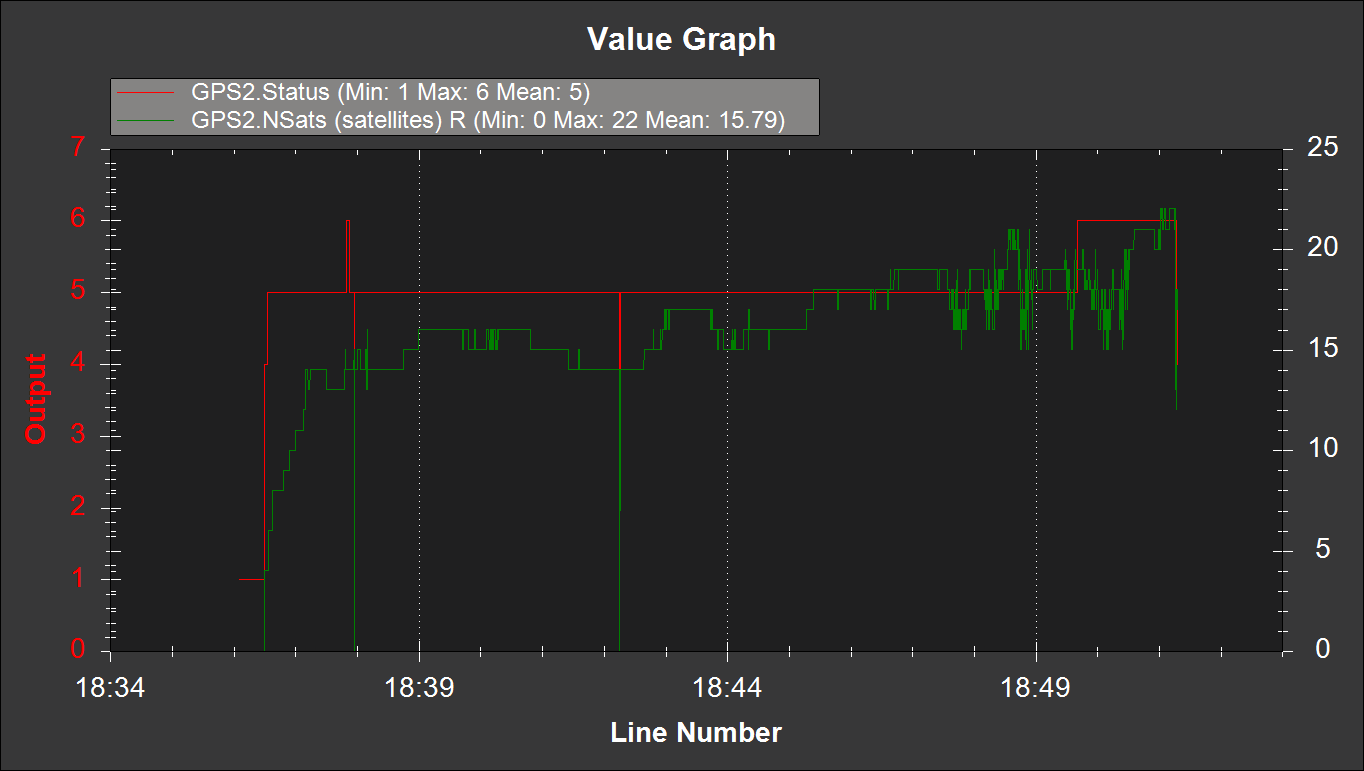
  2. I made some changes to the ZED-F9P RTK GNSS settings based on comments made on a prior post. I wanted to determine if these changes helped or hurt my ability to maintain an RTK fix.
  3. Being in a field with tall grass, I also wanted to push the envelope and see what the mower could cut effectively. The homogeneous fescue in my yard isn’t that difficult to cut.
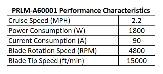
  4. Collect some general data about the mower’s performance. How much power does it actually use? How hot do the motors get after running for a while? How well does it mow autonomously?

Before I was using the mower deck, I only had two batteries in the battery bay. Loading and unloading isn’t too bad in this scenario: you can pretty easily drive the mower up the ramps and into the bed of my truck. With the other two batteries installed, that process becomes a little sketchier.

The wheel chair gearmotors have a neat little quarter-turn mechanism that disengages the output shaft from the rest of the gear train and lets the wheels spin freely, so I used this feature to push the mower up the ramps and into the bed of my truck. It’s too difficult to precisely maneuver the mower up the ramps and into the bed using the RC transmitter with the added battery weight.

Once in the field, I drove the mower out a safe distance away from the street to let it start working on an RTK fix. I wasn’t worried about absolute position, so I had the RTK base station configured to survey-in its location and used whatever it eventually settled on.

The first autonomous mission for the robot mower.

After I had an RTK fix, it was off to the races. I made a mission that was approximately a 100ft square and planned passes that were spaced 30in apart.

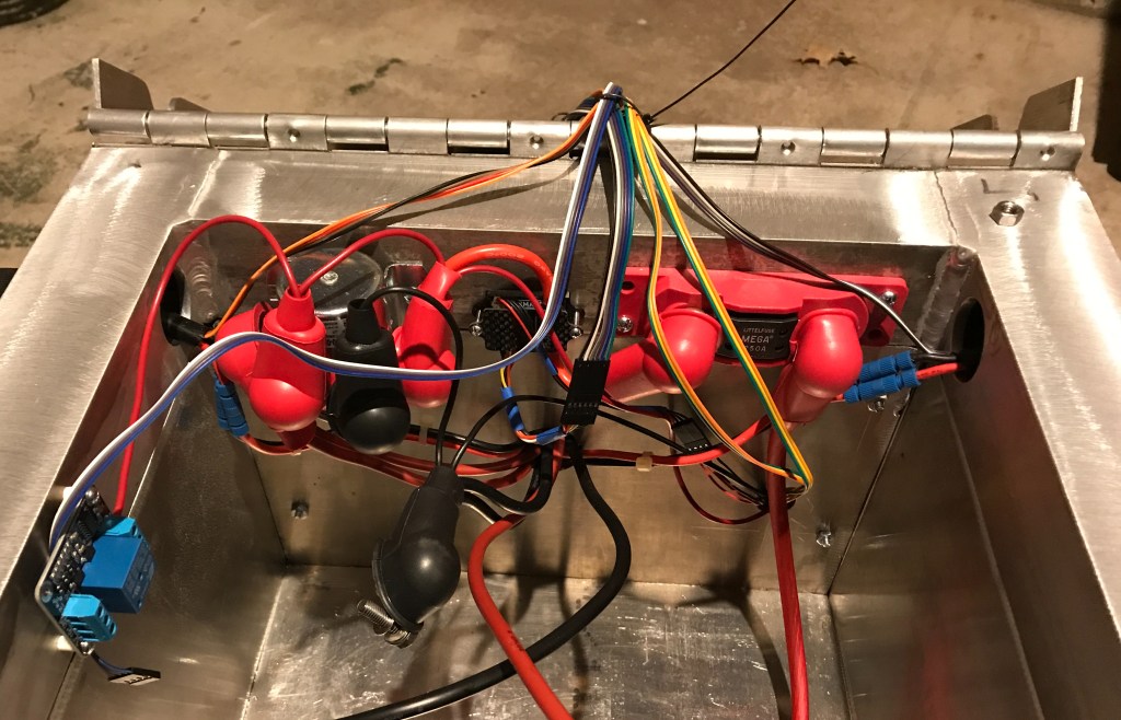
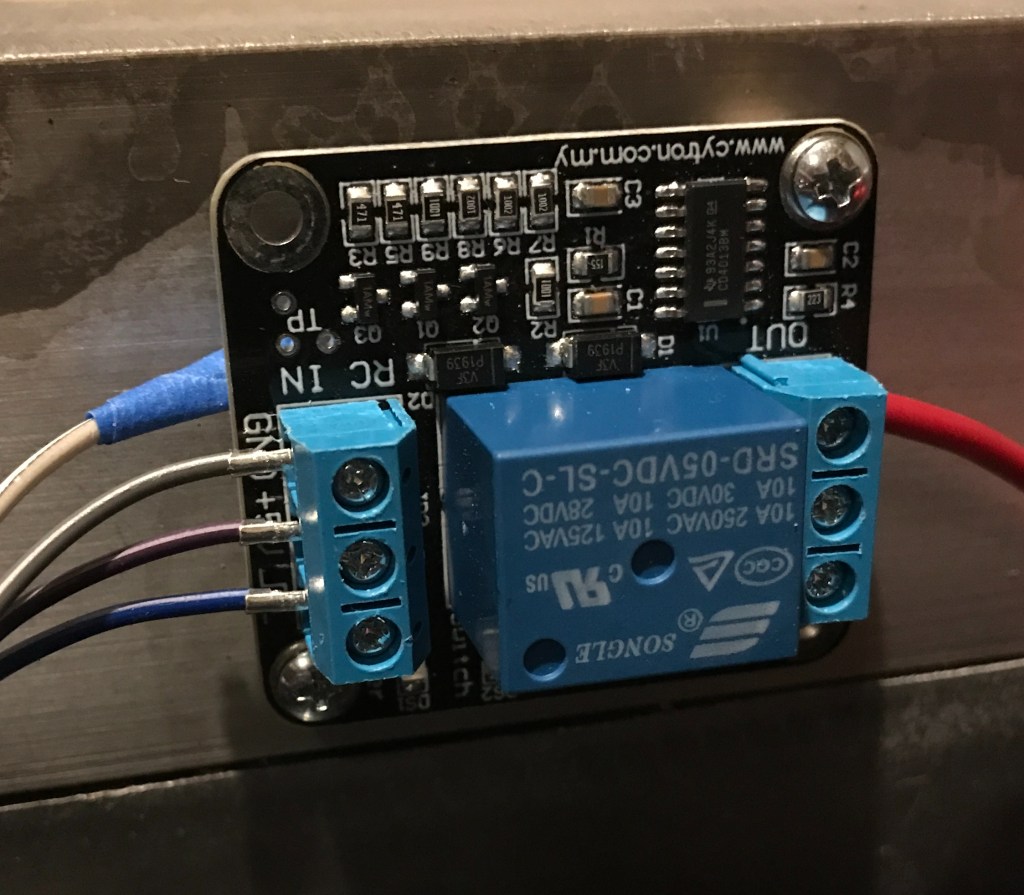
I configured channel 4 on my transmitter, the rudder stick, to control the power to my mower blades. This way it functioned as a dead man switch: if I let go of it, it would spring back to the neutral position. I designed relays inside the power enclosure to engage when the stick was held to the left. To keep the mower blades on, the stick must remain in that position.

After the mower made a few passes autonomously, I turned the blades on. That’s what you see in the video at the top of this post.

The cross track error was pretty large. You can see my tape measure lying in the grass for scale.

If the mower had maintained its position perfectly during the mission, each pass should have overlapped 6in because the mower deck is 36in wide and each pass was spaced 30in apart. Unfortunately, the mower’s position floated around by a fair amount. The un-mowed portions of the field are a result of this position error, which I’ve heard referred to as cross track error.

In some areas, the width of un-mowed grass was as large as 16in. This was a little disappointing. On average it was closer to about 8in. I need to find ways to improve the mower’s position estimate, so I don’t have to tighten up the spacing between passes.

The robot was using the magnetometer for heading, and you can see in the video that after each 180° pivot turn, the mower weaves a little bit as it tries to figure out its heading again. I intend to run another mission in the field soon with the magnetometers disabled to see if this improves the heading. Long term, I will look into using an additional RTK GNSS receiver to estimate the robot’s yaw.

This post is already pretty long, so I’ll make a separate one to review the logs and performance metrics I wanted to measure out in the field.

Vibration Issues (Continued)

The vibration in my mower deck is caused by unbalanced mower blades. The distance between the mower blade’s center of mass and the rotation axis of the motor shaft is often referred to as eccentricity, and this eccentricity results in a centrifugal force as the mower blade’s center of mass is swung around the axis of rotation.

A cheap prop balancer from Amazon with a 0.5in diameter keyed shaft from McMaster Carr. The two head press fit bushings ensures the keyway doesn’t interfere with the shaft’s rotation.

At high rotation speeds, even a small amount of eccentricity can result in a big centrifugal force. To see how far out of balance my mower blades were, I purchased a small RC plane prop balancer off the internet. With a few pieces of hardware from McMaster Carr I was able to get it to work with my mower blades.

One side of the blade was heavy, so I started putting scotch tape on the opposite side to see how much mass it would take to balance the blade. It soon became apparent I was going to need more mass than a few strips of tape, so I stuck a few #8-32 hex nuts on there. Once I got it pretty well balanced, I removed the tape and hex nuts and weighed them.

It took almost 3 grams of mass to balance one of my mower blades.

Because the mass of the blade assembly is not coincident with the rotation axis of the prop balancer, there exists a moment about the rotation axis when the center of mass is not directly below it.

By putting tape and hex nuts on the opposite end of the blade, we created an additional balancing moment. The sum of these two moments must be zero for a balanced blade at equilibrium.

We can measure the mass of the blade, which is 798.1g. We also know the mass of the balance weight, 2.8g. And we know the position of the balance weight: it’s half the length of the blade, 6in.

Using this information, we can solve for the eccentricity:

Calculations for determining the mower blade’s eccentricity, or the distance away from the rotation axis the mower blade’s center of mass lies.

And the resulting centrifugal force is:

The resulting centrifugal force if a mass of 798.1g is 0.021in away from the center of rotation at 4800RPM. I find some calculations are easier to do in SI units, making the conversion back to imperial units at the end.

To be fair, I didn’t get my motors up to 4800RPM. But at speeds near the natural frequency of a structure you get a lot of force magnification, so it’s entirely possible the mower deck was experiencing a force at least that large or larger.

I know what you’re thinking: that’s a lot of words to say “balance the blades, dummy.” But there’s a few reasons this exercise is valuable.

Firstly, it gives me a rough idea of how much material needs to be removed from the mower blade. It needs to be 2.8g lighter on the side opposite where we placed the balance mass. The volume of material that needs removed is:

The volume of material that needs to be removed from this specific mower blade assembly to align the center of mass with the rotation axis.

If the blade is 0.203in thick and about 2in wide, that means we need to grind the end of the blade down by about:

How much material that needs to be ground off the heavy end of the mower blade to achieve balance.

That estimation will hopefully save me a few trips between the blade balancer and the grinder.

Secondly, these calculations shed some light on how significant the imbalance is between the various blade assembly components. It’s not just the mower blade that’s unbalanced: the adapter, screws and even the motor shaft (it’s keyed on one side, after all) also contribute to the unbalance.

However, their combined mass is smaller than the blade’s mass, and their locations from the axis of rotation are also relatively small. For example, you’d have to add nine 1/4 washers to one of the mounting bolts on the blade assembly to offset the unbalance that exists in the blade:

The number of 1/4 washers you’d have to add to one of the mounting bolts to offset the imbalance inherent in the mower blade.

That stack of washers would be almost 5/8 of an inch tall and weigh 20.7g. So the lowest hanging fruit in our attempt to balance the blade assembly is going to be working on getting the blades themselves better balanced.1

And lastly, these calculations reveal a major flaw with my mower blade assembly design: nothing holds the blade fixed relative to the adapter. The screws are inserted through clearance holes in the blade, and if you loosen them, you can wiggle the blade around relative to the adapter by about 1/16 of an inch.

The bottom of the mower blade assembly. The two screws are the only thing that sets the position of the blade relative to the shaft adapter.

If 0.021in eccentricity already exists in the mower blade, and that creates enough vibration to peel open an eyebolt on my mower deck mounts at resonance, then any slippage of the blade during operation will easily re-introduce that vibration.

It might be worthwhile to redesign the mower blade adapter to locate off the center hole in the blade to prevent this from happening. And to also redesign how the mower deck connects to the robot chassis. But for now we’ll focus on balancing the blades and see what that does for us.

  1. Adding washers like this would likely change the orientation of the inertial axes and introduce couple unbalance. I’m unsure how significant this couple unbalance would be. While one or two washer shims might work for fine tuning the balance, attempting to eliminate the unbalance like this may create a situation where the blade is balanced statically but still vibrates when rotating.

Vibration Issues

Before using the robot mower, I always power the blade motors on in my garage for a few minutes to make sure everything is working right. I pulled our vehicles out of the garage, told the missus to expect some loud noises, and made sure that Mr. Mower Jr. was safe inside the house.

The nice thing about the new motor controller I’m using on the blade motors is that I can vary the rotation speed of the blades. So instead of commanding full throttle from the get-go like I had been doing with a relay, I decided to slowly ramp up the speed. It’s pretty incredible listening to the crescendo of the blades as they spool up.

About halfway to full throttle, I started to get a ridiculous amount of vibration. It was extraordinarily loud. The vibration was so intense that it peeled open the eye of one of my deck support eyebolts.

The eyebolt on the turnbuckle supporting the mower deck. The vibration was so intense it peeled it open.

At first, I thought this was just a fluke, or that perhaps the eyebolt was already close to failure, so I replaced it with a spare and repeated the process. I’m not very smart. The result was identical.

When I was in engineering school, I had a choice to take Design of Heat Exchangers or Vibrations and Acoustics for technical electives. As you can probably guess by looking at my mower deck design, I chose Design of Heat Exchangers. It was a fun class, but pretty useless for anything mower related.

So to work through this issue, I’ve had to do some homework. Lucky for me, I managed to stumble upon a copy of Timoshenko’s Vibration Problems in Engineering at the Goodwill a few years ago, which has proven a valuable resource in my vibrations education.

Timoshenko says it better than I can, so I will quote him directly:

By an impulse or sudden application and removal of an external force, vibrations of the [spring mass] system can be produced. Such vibrations are maintained by the elastic force in the spring alone and are called free or natural vibrations.

Vibration Problems in Engineering, page 1

The mower deck is a kind of spring mass system, though geometrically more complex. There is a frequency at which it will vibrate if you were hit it with a hammer, just like a tuning fork will vibrate at 440Hz if you strike it against a hard surface. That unique frequency is called the system’s natural frequency, or frequency of free vibration.

Unfortunately, we’re not just hitting the mower deck with a hammer once. We’re hitting it with a hammer 4800 times per second. That oscillating force does not allow the mower deck to vibrate freely. That’s not free vibration. It’s forced vibration.

In the case of the mower deck, the frequency of that forced vibration is whatever speed the motors are spinning at. Because the motors go from zero to 4800RPM, the mower deck experiences vibration at every frequency along the way. Chances are good that the motors will create forced vibration at the natural frequency of the mower deck at some point as they spool up to operating speed.

A very curious thing happens when you force a structure to vibrate at it’s natural frequency. You get resonance. And the amplitude of vibration becomes very large at resonance. Absent damping it will become infinite. Timoshenko includes a chart that illustrates this phenomenon very well.

Resonance, and the Magnification Factor, from Timoshenko’s Vibration Problems in Engineering, page 42.

When I was spooling up the mower deck motors, I consciously decided to do it slowly to minimize electrical current spikes. This created a problem that didn’t previously exist with the relay, where we rapidly turned on the motors. Timoshenko explains:

The amplitude of vibration [at resonance] increases indefinitely with time… This shows that, while we theoretically obtain infinite amplitude of forced vibration at resonance in the absence of damping, it also takes time to build up these large amplitudes.

Vibration Problems in Engineering, page 48

In other words, if we maintain forced vibration at the natural frequency of a structure, the amplitude of vibration will increase continuously to the extent allowed by any damping present in the system.

By slowly increasing the speed of the motors, I was allowing the mower deck to experience resonance and the accompanying large vibration amplitudes for a period of time long enough to damage the turnbuckle eyes. Who’d have thought?

Something else I noticed was that I had trouble getting the motors to speed up once they were at speeds close to the mower deck’s natural frequency, when it started vibrating really bad. Timoshenko has something interesting to say about that, too:

Experiments show that if any vibrating system is once allowed to reach a steady state just below resonance, it then becomes difficult to accelerate the machine through the resonance condition. Additional power supplied for this purpose is simply used up in increasing the amplitude of vibration rather than the running speed of the machine.

Vibration Problems in Engineering, page 48

I think I have a good grip on what the problem is. Next post I’ll discuss some things that can be done to mitigate this surprising issue.

Wiring Improvements

I’ve spent most of this winter re-wiring the robot mower. In hindsight, I should have spent a lot more time planning the wire runs. I made a lot of design choices about how the chassis should look and where enclosures should be located that are inappropriate given my more complete understanding of how the wires need to be connected between components.

At some point you have to build something that’s not perfect and work through the bugs later. It’s against my nature to operate that way, but if I hadn’t started building the robot mower in reality at some point, it would still be a picture in my CAD program.

In the rest of this post, I’ll describe some wiring related improvements I’ve been making to the robot mower.

The original power enclosure. The phrase “rat’s nest” comes to mind.

The picture above is how the power enclosure used to look. It used to contain the Sabertooth 2X60, the voltage/current sensor, the BEC, a positive and negative terminal stud, a small 5V relay board to trigger two larger 50A relays, a power switch and an XLR charging port. It was a mess, to say the least.

The reorganized power enclosure. No relays or terminal studs, just two motor controllers and a BEC.

The reorganized enclosure contains the Sabertooth 2X60, the BEC, power switch, XLR charger port, and a motor controller for the deck motors exclusively.

The reason I tried to pack so many components into the power enclosure was so I didn’t have to put anything other than wires in the battery bay. It is a battery bay, after all. I was hoping to make an entirely modular power enclosure I could build up separately from the robot and then basically bolt on.

While that’s nice in the CAD software, in reality it didn’t work. If I’d selected a larger enclosure it might have been possible. But an unintended side effect of putting everything in one enclosure is that you have to run 24V and ground into the enclosure, but you then turn right around and run a ton of wires right back out of the enclosure.

As I have learned, relays are not a great way to control motors, especially if they’re using a lot of power. And on top of that, those “200A” relays were kind of a scam. They terminals are only rated for 50A, and I’m pretty sure I managed to fry one out in the field. I decided to replace them with a single channel motor controller that can supply up to 200A of current.

The nice thing about having a motor controller driving the deck motors is that I can dial back the blade speed if the mower is cutting the grass just fine. There’s no sense in running at 4800RPM when 3600RPM will do the job. I’m hoping this will allow the robot mower to run for a longer period of time.

A fuse block for the mower deck motors.

I was using wire nuts to connect all of the deck motor wires together originally. I wanted to make things a little more professional than that, so I decided to replace the wire nuts with a fuse block.

In theory, the deck motors should only use about ~30A each at steady state, and with the new motor controller, I think I can spool them up slow enough to where a fuse doesn’t blow. We’ll see how good this assumption is soon.

One thing I like about the fuse block is it allows me to easily disconnect power from the deck motors: just pull the fuses. This makes safe troubleshooting easier. The fuses will also provide a layer of protection for the motor controller. But at the same time, a blown fuse creates exactly the situation that caused my wire failure. I intend to also have a Zener diode between the supply terminal and ground to hopefully protect against this situation, too.

Components relocate into the battery bay. From left to right, there’s an RC controlled relay board, a solenoid, the voltage/current sensor, and a master fuse block.

All of the power in the robot now runs through a MEGA fuse, and from there it runs through the voltage/current sensor. After that, it runs through a solenoid, which supplies power to the drive and deck motor controllers. The solenoid can only be powered if the E-stop switch and RC relay board are in safe states.

I also put rubber boots on every exposed terminal, including the batteries. They look a little ridiculous on that solenoid, but they are adequately insulated.

The RC controlled relay board.

The RC relay board is controlled by a switch on the RC transmitter. If the RC relay board doesn’t detect a valid RC signal, it will open the relay. This allows me to have a remote E-stop switch.

One thing I don’t like about this RC relay board: when you power it on, it automatically closes for a second, then goes open. That’s a really crappy design, in my opinion. But without the Pixhawk armed it’s kind of a moot point.

A proper ground plane for the GNSS antennas. The foil to the left was what was underneath the RTK GNSS receiver previously.

I also finally got around to putting a proper ground plane under my GNSS antennas. We’ll see how much this improves performance.

I hope to have these wiring improvements wrapped up soon. The grass is green and growing out here in Kansas!

Inductive Kickback

I’ve learned a lot about the behavior of DC motors from the book Introduction to Mechatronic Design. Much of what I will discuss in this post comes from chapter 20 of this book. Electrical engineers reading this post will laugh at how elementary some of this information is, but it was news to me as a mechanical engineer.

I find that I solidify my understanding of ideas and concepts by writing about them. So what follows is a brief book report on a phenomena often called inductive kickback, which I believe was the cause of the wiring failure on my robot.

A motor is an inductor. Inductors store energy in magnetic fields. When you apply voltage to a motor, a magnetic field is created around the motor. A unique characteristic of inductors is that they resist changes in the flow of electricity through them.

If you were to suddenly disconnect the voltage source, the magnetic field would try to keep electricity flowing through the motor. But because there is no where for that electricity to go, the voltage across the motor terminals increases instead. And it can increase to very high levels, sometimes thousands of volts.

A typical graph of Inductive kickback voltage from Introduction to Mechatronic Design.

The energy stored in the motor’s magnetic field has to go somewhere. What usually happens is the voltage becomes high enough across the motor terminals that a nearby component becomes a target for electricity to arc through and flow out of the motor.

I didn’t state it in my previous post, but to power on the deck motors I’m using a large relay. To turn them off you have to open the relay, and you end up creating exactly the inductive kickback situation described above. And with nowhere for electricity to flow, I think the voltage between some of my wires became so large that it arced through the insulation.

What could have been the ignition source for a Kansas grass fire, save for my 100A fuse.

The damaged wires in the picture above are the + voltage wire on the motors and a battery ground wire, curiously enough. And notice how close they are to each other: a perfect place for electricity to arc. Better than the contacts inside the relay, which was still functional, surprisingly.

I now know why wires are voltage rated: it has nothing to do with the conductor material or size, and everything to do with the insulation. The insulation will only prevent arcing below a certain voltage threshold. And in the field several weeks ago, it looks like I greatly exceeded that threshold, whatever it was for those wires.

I checked the Posi-Lock website, and their connectors are rated for 600V. I don’t remember where I got my wire from. I’m sure it was the cheapest knock-off stuff I could find. The insulation has no identifying marks, so I’m not sure it’s voltage rated at all.

Next post I’ll describe the changes I’m going to make to robustify the wiring and electrical components in the robot mower.

How Not to Wire Up a Robot

What could have been the ignition source for a Kansas grass fire.

If you look closely at the charts in the previous post, you’ll notice they end quite abruptly. The picture above shows why.

I have the robot mower configured so the blades only turn on when you hold the rudder stick to the right. The stick is spring loaded, so letting go of it returns it to center, deactivating the blades.

A typical shrub out in the field. Most were about 18in tall.

The field I was testing in had several large shrubs in it. One of my goals in the field was to push the envelope on what the mower was capable of cutting through, so I let it mow over several of them in autonomous mode. However, there was a particularly large shrub in the robot’s path, and so I decided to turn the mower blades off by releasing the rudder stick.

As expected, the blades stopped. But the robot stopped moving, too. This was curious: the robot should have continued driving. So I pressed the emergency stop button on the robot to immobilize it, and walked over to the truck where I had Mission Planner running on my laptop.

A screenshot of Mission Planner telemetry log after I returned to the truck. The reported voltage is 12.50V.

The Mission Planner screen was frozen as if it wasn’t receiving telemetry from the robot. It took me a few minutes to realize that the issue wasn’t Mission Planner or my laptop radio: it was that the robot wasn’t sending telemetry. And even more curiously, the voltage reading on my SLA batteries said 12.50V. I was worried that I’d really fried my batteries, so I walked back over to the robot to investigate.

Opening the battery bay I found a slight amount of smoke and that awful burnt plastic smell from melted wire insulation. But other than that everything seemed fine. There wasn’t a smoldering fire inside the robot. The batteries weren’t hot to the touch.

At first I chalked it up to too much current running through the wires. The robot uses 120A at peak current, and at those levels even a small amount of resistance could cause the wires to heat up a lot. Perhaps the wires just got hot enough to melt the insulation and came into contact right at the moment I decided to shut the mower blades off?

One of the melted wires. The yellow blob on the end is a portion of a Posi-Lock.

This just so story didn’t sit well with me. What an awful coincidence that the wires failed at exactly the same moment I was shutting off the motors, especially after the robot ran fine for five minutes prior. Why didn’t they fail earlier?

Additionally, why didn’t the exposed wire conductors fuse together after they came into contact? I’ve heard of people using SLA batteries smaller than mine to spot weld 18650 battery tabs together. The wires were really close together, but weren’t touching when I opened the battery bay. And the wire strands don’t seem to be melted judging from the picture above. Which was extraordinarily lucky, given how bad that could have been.

I did have enough sense to put a 100A fuse on my batteries. It seemed logical that the fuse was what saved my bacon. But using the multimeter to test the fuse revealed that it was not, in fact, blown. At this point I was completely bewildered. I thanked the good Lord that the robot hadn’t turned into a massive lead acid fireball, made sure all my batteries were all disconnected, packed up, and went home.

I’m sure readers are ready to scold me for all of the janky things going on in my battery bay, and I certainly deserve that criticism. My mantra is make it robust, and I definitely did not live up to that standard with my wiring. Below is a full picture of the battery bay.

The robot mower battery bay. How many janky things can you spot?

I have my own list of janky things in here that I intend to fix. What do you see that is janky? Feel free to comment below!

In the next post, I’ll explain what I think went wrong, and the improvements I’m going to make to mitigate the problem and eliminate all the redneck wiring I’ve got going on.

Robot Mower Performance

I didn’t spend much time in the field testing the robot mower, but the little time I did spend gave me a treasure trove of information about how the robot mower performs. Below are some high-level measures.

Performance characteristics for the robot lawn mower in the field.

I set the robot cruise speed to 1m/s or 2.2mph. I’ve run the robot mower faster in manual mode, but for obvious safety reasons, a moderate walking pace seemed best. If the robot gets out of control, I want to be able to catch it.

I am using a Mauch PL-200-HV current sensor on the robot. The sensor is connected to the positive terminal on my batteries, so it reports the total current used by robot: sensors, drive wheels, mower deck motors, etc. Once the mower is spooled up, current consumption levels out at about 90A.

Current consumption used by the robot mower.

The first portion of the graph above is the robot mower operating autonomously without the deck motors turned on. The huge spike is when the deck motors get turned on. It’s curious it says the peak is 196A: the PL-200-HV is only rated for 200A. I wonder if the spike was actually larger than shown, but due to its current rating, the sensor only reported ~200A.

There is a surprising variability to the amount of current used by the deck motors. In the garage, the deck motors would use 46A +/-1A. It was kind of impressive how steady current consumption was. But throw some grass under the robot and you get a ton more variability. Current consumption for the whole robot varies from 65A to 120A with the deck motors on.

Grass is typically pretty homogenous, even out in the field, so this was unexpected. I went and reviewed the logs from my backyard, and they look about the same. Even controlling for pivot turns at the end of a pass, the current consumption is all over the place.

Current consumption versus steering commands. Each spike on the green line is the robot mower making a pivot turn at the end of a pass.

It does appear to dip a little with each turn, but only ~15A. Maybe I’m reading into it too much. There were some small shrubs and some pretty gnarly crab grass plants out in the field. The current variation might just be the mower running over those things.

I also wanted to see how much the battery voltage dropped when running the deck motors in a real-world situation.

Battery voltage level before and after the mower deck motors were turned on.

I made sure all four of my batteries were individually fully charged before going to the field. But any way you cut it, asking 90A out of four 35Ah SLA batteries is pushing it. With the deck motors on, the nominal battery voltage drops to 20V.

I toyed with the idea of using lithium ion or similar batteries from the start when designing the robot mower. But they’re pretty pricy, and for the time being, SLA batteries will work well enough for field testing. The four 35Ah SLA batteries were less than $200, so I can afford to run them like a rented mule.

To get the total power consumed by the robot you need two things: current consumed and the voltage level when it was consumed. Mission Planner will do the math for you by multiplying the current and voltage at each time step and then adding them up for a total energy consumed graph.

A running total of the energy used by the robot over time. Find the slope of that line and you’ve got the average power consumption over that time period.

Unfortunately, Mission Planner won’t differentiate that graph for you so you can see what the power consumption was at any given time. But if we assume the power consumption is linear over the five minute time interval above, we can estimate it.

A simple way to calculate the power consumption for the robot mower.

This number is encouraging. I’ve seen the drive motors on typical electric riding mowers consume more than 1kW by themselves, excluding the deck motors. I need to do some more testing to see how efficient the robot mower is on less flat terrain. But as you’d expect, there appear to be a lot of power savings to be had by getting rid of the guy riding the mower.

Regarding the blade motor rotation speed, there are two ways I can think of to estimate this. One way is based on the current consumed by each motor. Take that number to the motor performance charts and you can estimate rotation speed.

The other is to see at what frequencies the mower is vibrating at. Thanks to some new developments by the Ardupilot folks, this is a pretty straightforward task. If you can find the frequency where you get strong vibrations at, you can assume that’s the probably speed at which the motors are rotating.

The mower uses about 5A when running without the blade motors on. That means all three motors consume 85A, or each motor consumes 28A.

Performance curves for the AmpFlow E30-400 DC motor.

At 28A of current consumption, an E30-400 motor spins at 5100RPM, uses 540W of power and and achieves 1N·m or 0.74ft·lb torque. One of the big question marks in the robot mower design has been how well the motors would perform. It appears they’re just about perfect, operating right at the peak of its efficiency curve.

Speaking of efficiency, one thing I did notice about the deck motors was that even after a few minutes of operation, they were very hot to the touch. So hot I couldn’t keep my hand in contact without significant discomfort. Yes, I did try. I’m guessing they were north of 140°F.

Even if the motors are 79% efficient, that means that 21% of that 540W, or 113W, gets turned into waste heat. That’s a fair amount of heat to dissipate through a 5in long, 3in diameter cylinder by free convection. It might be worthwhile to come up with some kind of cooling fin to attach to the motor housing.

Ardupilot now has a feature that lets you analyze logs to see where vibration issues might exist. It looks at data recorded by your IMU and does a fast Fourier transform on the data to find frequencies at which you have high levels of vibration.

Using this method to estimate the motor rotation speed gives you several graphs that look like the one below.

The amplitude of vibration in the X, Y and Z directions on the robot mower across the frequency spectrum.

My understanding is that this graph gives you the strength of vibration at certain frequencies. I am unsure of the units on the Y axis. I think they’re m/s, but that seems awfully high. But then again, the mower deck is basically a giant vibratory table. I have no reason to believe they’re not accurate.

One thing that is interesting to note is that the amplitude of vibration is high in the X and Y directions across the spectrum, but less so in the Z direction. I think X is the forward to aft direction and Y is the left to right direction on the robot. So high levels of vibration along those axes makes sense when you think about a giant unbalanced motor rotating along an axis perpendicular to those two directions.

I’m assuming that all three motors are spinning at close to the same speed, but in reality, I’m sure they’re all off by some amount. I’m not sure how that affects the accuracy of this method of estimating the mower blade speed. Regardless, 4680RPM jives with the estimates obtained from the motor chart. The truth is probably somewhere in the middle, perhaps 4800RPM.

The calculation for blade tip speed with a motor rotation speed of 4800RPM and a blade length of 1ft.

15000ft/min is well below the 18000ft/min limit that manufacturers abide by. But judging from the good cut quality in the field, it might be possible run the motors slower. This would reduce the power we need to run the robot. AmpFlow makes a motor that is identical to the E30-400 that is a little bit shorter and uses less power. I might see if it would make sense to use this motor instead.

The fix status for the ZED-F9P GNSS module. 6 is RTK fixed.

I made some setting changes to the RTK GNSS modules based on some great comments I received a few posts back. I outlined those changes in this post. After that post, I made one additional change to the CFG-NAVSPG-DYNMODEL configuration item. I set it to 3 = Pedestrian.

The graph above shows the RTK fix status. The changes I made in that post resulted in a rock solid RTK fix. The little dips in RTK status were less than a second in duration. Thank you to Sean Smith and Frank Beesly for their valuable feedback!

The magnetometer performance was more or less garbage. I think a good portion of my cross track error is due to the compass variance corrupting an otherwise good position solution given by my wheel encoders and RTK GNSS.

Reviewing the telemetry logs, before I was even in autonomous mode, the EKF was reporting a marginal compass health reading. And the chart below tells you all you need to know about the rest of the compass performance.

The magnetometer’s reported Y magnitude versus the total current used by the robot.

The reported magnetic field strength jumps by 0.15 Gauss after you turn the deck motors on. It might be possible to zero this out in the software by finding the offsets when the deck motors are on, but I have so little confidence in the magnetometer at this point, it’s not worth the effort in my opinion. RTK GNSS yaw seems like a much more robust solution for heading.

Keen observers will notice something peculiar at the 17:16 mark on these graphs. More on that in the next post.

Mower Blades: More Complex Than You’d Think

ego-lawn-mower-blades-ab2000-64_1000
A typical mower blade.

While designing the robot mower, I spent a lot of time working on the chassis, electronics enclosures, and wire routes. I tried hard to select components I could easily acquire at a reasonable cost, and that effort paid big dividends when I went to get everything built.

Unfortunately, I didn’t spend nearly as much effort on how the mower blades would attach to my motors, or even what the mower blades would look like. I assumed I could easily find any mower blade size I would need, or that making my own custom blades wouldn’t be difficult.

Now that the blades are the only thing missing on the robot mower, I’m realizing how mistaken that assumption is. I designed the mower deck for three 12in long blades, thinking that surely such a size exists. But most blades are generally in the neighborhood of 20in long.

Small gasoline powered mower engines operate at speeds in the range of 2,500RPM to 3,000RPM, and to achieve an appropriate blade tip speed slightly less than 19,000ft/min, the math forces you to use a blade that is between 19in to 22in long. Blade sizes outside this range aren’t common.

Initially I decided this wasn’t an issue: I’ll just make my own blade. It’s just bar stock with two sharp edges, right? Well, kind of. There’s a fair amount of metallurgical considerations that go into mower blade fabrication. On the one hand, you want a soft, ductile blade that doesn’t shatter when it hits a rock or tree stump. But on the other, you want the blade to be able to keep a sharp edge for a long time, which means making the blade, at least near the sharp edge, more brittle.

Cutting grass creates an inherently moist environment under the deck, so mower blades are usually painted or feature some kind of corrosion resistance. And on top of all this, a good blade will have a small bend opposite the cutting edge to create a little wing so that the grass clippings can be pulled upward resulting in a nice, even height cut.

The more you learn about mower blades the more you start to realize that buying one is really the way to go. In your research you’ll come across horror stories of guys who made their own mower blades and either welded them poorly or jury rigged them to work and then got hurt or even killed by the shrapnel from a blade shattering. Just this video alone should give you pause: there’s a lot of energy under a mower deck.

So off I went to find a 12in long mower blade. The closest I could find was one that was 12.125in long, which leaves 0.375in between the blade tips when they rotate past each other instead of the 0.625in I had designed for. We’re about to find out how accurately the mower deck weldment was made. I really hope I don’t have to grind the ends of the blades down because they crash into each other.

Finding a blade is only half the battle. How do you attach it to the 0.5in diameter keyed shaft on the E30-400 motor? The crankshaft on most push mowers I’ve seen has a threaded hole in the shaft for bolting the blade on. The E30-400 has nothing of the sort.

Could you drill and tap a hole in the end of the shaft? Possibly. But a #10-24 threaded hole is about the biggest you could drill and tap, and that only gives you 0.083in of edge margin from the major diameter of the threads to the keyed portion of the shaft. Too close for comfort in my mind.

The first solution that I came up with was to take a piece of 1.5in long, 2in diameter round stock, bore a 0.5in hole in it, key the hole, and then drill and tap holes for mounting the blade and some set screw holes to clamp the key up against the shaft. But in this scenario, the set screws are the only thing that holds the blade on the shaft. Better than nothing, but not by much.

combined
My first idea for a mower adapter: a machined piece of round stock. Expensive and heavy, not what you want in a blade adapter.


I got a few quotes on three of these parts and the keyway really kills you on cost. I got several no bids because of the keyway alone. And the quotes I did get back were pretty high. Because I don’t like spending $300 on blade adapters, it was back to the drawing board.

What I really need is something with a keyway already in it. Initially I looked into some keyed pulley bushings, but they too have no way to hold themselves on the shaft. That and they have to match your hole pattern on the blade, and none of them met that criteria. They’re cheap, which is nice, but don’t really work for this purpose.

Eventually I got turned onto the idea of using solid shaft couplings. They’re keyed and include set screws. But the outer diameter for most half inch couplings is 1.5in or larger. That leaves no clearance for the bolts to mount the mower blade, which are 1.625in apart.

IMG_6250
A 0.5in ID X 1in OD solid shaft coupling with four set screws. McMaster has them for $16 apiece, but if you search on eBay you can find them closer to $6.

After some more digging, I found these smaller OD shaft couplings. And on top of their 1in outer diameter, they come with 2 pairs of set screws offset by 90°. Not bad! Take one of them and weld it to a plate with a hole pattern matching your mower blade, and you’ve got a custom mower blade adapter for ~$30 a piece after material and labor. The result looks like this:

the best option
The 1in OD shaft coupling welded to a plate. The cotter pin keeps the coupling on the shaft.

The nice thing about the plate is that you can get a lock nut on the back side. I’m less worried about things vibrating loose compared to the machined adapter where the bolts run straight into a threaded hole.

But even with four set screws clamping up against the shaft, you really need some positive retaining feature to make sure the blade stays on the shaft. To meet this design objective, I figured it’s best to keep things simple: drill a small hole perpendicular to the coupling and the motor shaft, and then run a small hairpin through it. You don’t need a big one to keep it on the shaft.

The hairpin will add a little bit of eccentricity, as will the set screws. How much? I guess we’ll find out soon. Once the parts get back from the shop I’ll post some graphs and pictures.

An Even Better RTK Fix

Several comments on my post about the RTK GNSS results I experienced in the parking lot have made me reconsider how good my RTK fix really was. I was able to get a fix pretty easily, but it was fragile, and would frequently drop back to float without any apparent change in the environment. 

When searching for ways to improve the robustness of the RTK fix, I came across this very comprehensive discussion about u-Blox receiver settings. The consensus I gathered from the discussion was that there are two configuration changes on the ZED-F9P boards that can really improve your RTK fix robustness: tightening up the elevation mask and increasing the signal to noise threshold.

To change these settings, I connected the ZED-F9P module via USB to my computer and then connected to it within the u-Center software. I then went to View > Generation 9 Configuration View. I double clicked on the Advanced Configuration on the left pane to show all the various configuration items.

You can use the CFG-NAVSPG-INFIL_MINELEV configuration item to set the elevation mask. This angle is measured from the horizon upwards. Satellites below this elevation are excluded from the navigation solution. The default is 10°, which I changed to 15°.

You can use the CFG-NAVSPG-INFIL_MINCNO configuration item to set the signal to noise ratio. The default is 6dbHz. I set mine to 35dbHz.

It was kind of a pain to remove the module from the robot, connect it to my laptop, change the settings, and then replace it in the robot, so I didn’t do any A-B testing on these values, although I may in the future. The 15° elevation mask and 35dbHz signal to noise values were recommended from the discussion linked to above.

I did do an A-B test on an aluminum foil ground plane to see how that would improve the fix quality.

IMG_6167
An aluminum foil ground plane underneath the RTK GNSS antenna.

Below is the results with and without the ground plane. Initially I had the robot parked in my driveway under some trees, but after waiting more than 10 minutes for an RTK fix, I decided to drive the robot out in the street where there was a better view of the sky. Shortly thereafter, I got a fix.

no foil ground plane nsats + status
The RTK GNSS performance without a foil ground plane. Left vertical axis is fix status where 6 = RTK fixed, and right vertical axis is the number of satellites seen by the receiver.

But with the foil ground plane, I was actually able to get a fix in my driveway under the trees. I drove the robot along my street at about 2:30 to see how robust the fix was. Much fewer hiccups, even with a more challenging environment.

With foil ground plane nsats + status
The RTK GNSS receiver performance with a foil ground plane.

I ran the same mission down my street and back with and without the foil ground plane. The ability to keep the RTK fix with the foil was quite surprising. It’s definitely an improvement.

I will take these settings and foil ground plane to the parking lot soon and see how they perform.

The Right Problem

When I mow my lawn, I spend five minutes putting on mowing clothes and walking out to the garage to grab the mower, and this experience has influenced the productivity solution I think the lawn care industry needs. The pain I experience involves pushing the mower. Lawn care companies, on the other hand, experience pain in a whole host of other areas. The two situations are worlds apart, and the comments on my last post made that crystal clear. Thank you to those who shared their thoughts!

As I think about these ideas, I’m starting to realize the problem I’m solving really isn’t the right one. The tag line on this blog is “a project devoted to an autonomous lawn mower.” But the real goal is actually increasing lawn care productivity. An autonomous mower is only a means to accomplish that goal.

Greenzie and Mowbotix haven’t succeeded yet because they haven’t built a system that increases lawn care productivity. While they have successfully removed the operator from the mower, they’re making a mistake by trying to sell it to lawn care companies. Integrating an autonomous lawn mower with the way lawn care companies operate today actually makes them less efficient.

Lawn care companies are just as much about logistics as they are about mowing grass. Successful lawn care companies are able to quickly ferry workers and mowers to multiple job sites throughout the day. But to do this they use expensive tools: a truck and a trailer. And beyond the cost of the truck and trailer, they also waste a lot of time travelling between job sites.

These are major costs that get baked into the price people pay for mowing services. Which is great: it means that there is a lot of waste in the way lawns are currently mowed, and that it’s possible that a new way of mowing lawns can exploit these inefficiencies for profit.