It appears the root cause of the right motor not responding at all to RC input was actually a lot simpler than I imagined. I should have caught it early, and the fact I didn’t is a little embarrassing.
Mission planner usually says that the motors are drawing approximately 5A to 7A so I generally assumed the motors weren’t under that much load. I am now questioning those readings given the damage to the board, shown below.

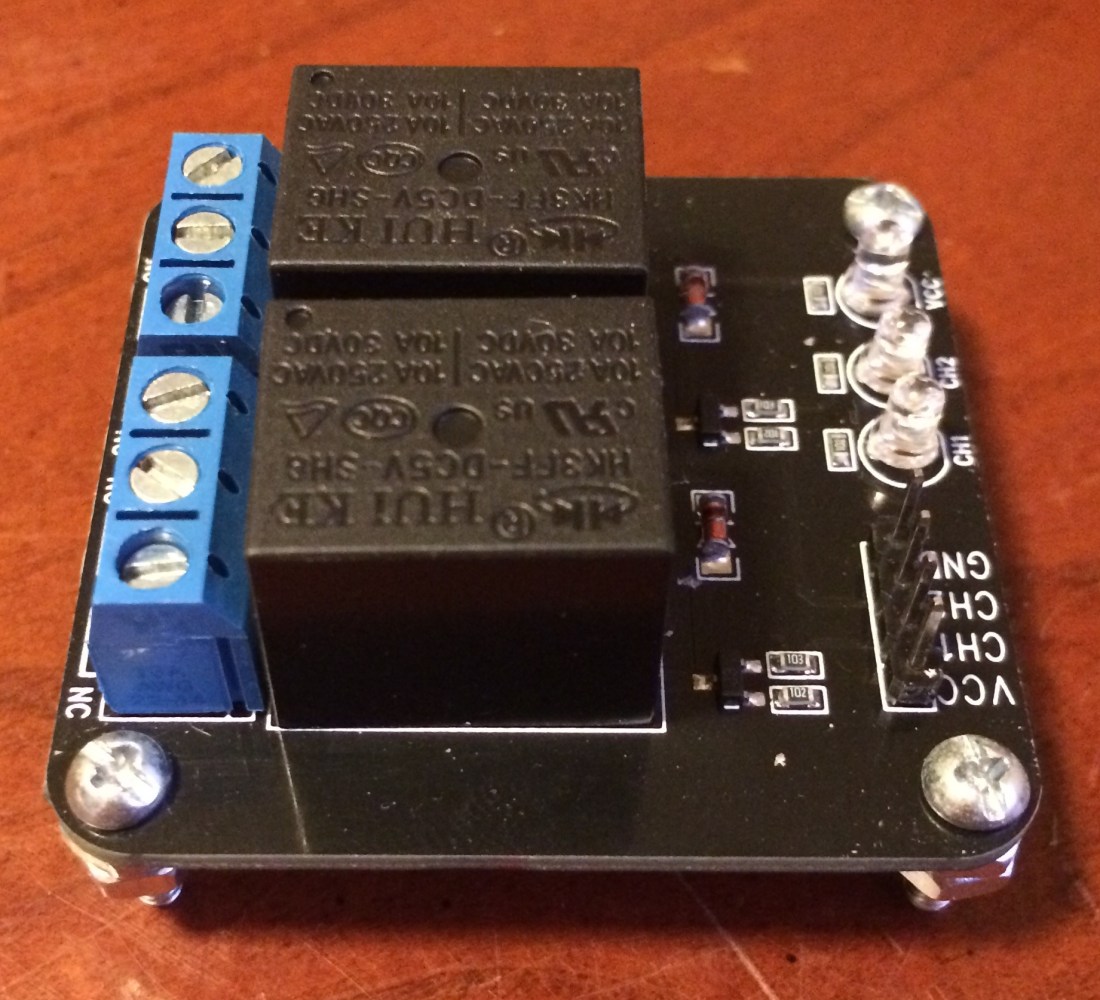
I remember checking the relay board after one of the motors stopped working, but I was relying on the LEDs to confirm the relay was triggering properly. This was the wrong way to check the board, because the LEDs light up when 5V is applied to the header pins, not when the relay actually closes.
I also seem to recall hearing the relay “click” when triggered, but because the wire trace in the board was burnt up, no current could flow through the board, whether the relay was engaged or not. Because the back of the board was hidden and I couldn’t see the burnt up wire trace, I assumed the relays were good and moved on. I’ll check the module later, but the relays probably still work fine.
Lessons Learned
My Mission Planner current readings are probably wrong.
I don’t think I have the current sensor calibrated or configured properly. Either that, or mission planner does some kind of smoothing of current measurements that doesn’t reveal maximum current flow, only the average over the measurement period. The Mission planner output is total current consumed by the robot, meaning 7A is used for everything. This shouldn’t have caused a problem, in theory. Obviously, there is a disconnect between reality and theory somewhere.
You get what you pay for.
This relay board was $3 plus shipping. The header pins were a nice setup, and the fact that the relays could be triggered with 5V is the main reason I bought them. I had a convenient 5V source to switch them with, so I tried to keep things simple. Unfortunately the board was undersized for the task, as you can even see heat damage to the conductor that isn’t completely split. I should have known there was a problem when I couldn’t fit 12ga wire into the screw terminals on the board and had to use 16ga wire instead. Not good.
Fuses are critical for protecting components and preventing fire.
I’ve been skeptical of going to the trouble of putting fuses in my robot, partly from a cost perspective but mostly from an “ain’t nobody got time fo dat” mentality. This failure could have been a more critical component. If the relay board hadn’t failed, I could have fried the Sabertooth, or worse, started a fire in the enclosure. While I’ve focused my safety efforts on the spinning blades, this is an equally important area to get right.
Remember Occam’s Razor when troubleshooting.
When one motor spins but the other one doesn’t, which is more likely:
- The Sabertooth motor controller is fried, but only halfway fried.
- There’s a connectivity problem to the motor that doesn’t turn.
Taking a step back to asses the problem can save a lot of useless troubleshooting, like tearing the Sabertooth out and testing it. Use common sense. Start checking the simplest failure modes first, moving to more complicated failure modes until the root cause is found.
Going Forward
To switch current to the motor controller I am going to add a much larger 50A relay to this system. I’ll then use one of these smaller boards to switch the 50A relay. The coil current consumed by the 50A relay should be much lower than the current consumed by the drive motors on the robot.
