I’ve received a few of the weldments back from the shop. While I wait for them to finish fabricating the mower deck weldment I’ve started to put some components together.

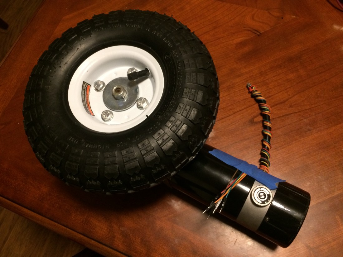
Back when I installed the wheel encoders on the wheel chair motors, I stupidly drilled a hole through the dust cover on the back of the motor so I could run data wires to the encoder. In hindsight, I should have run them through the little sleeve that the power and brake wires were routed through.
I had to take the brake off to put the encoder on the motor anyway, so there was a perfect amount of space for the encoder wires once the brake wires were removed from the sleeve.
Because you can’t undrill a hole I purchased a pair of cheap gear motors off eBay for $80. I mostly wanted them for the motor dust cover, but it will be nice to have spare parts on hand in case I need them down the road.
I took the aluminum back piece off the motors and removed the two white wires you see in the picture. The hole you see them sticking through was where I routed the data cables for the encoder.
Pro tip for dealing with these motors: There are two Philips head M5x150 screws holding the aluminum back piece to the mounting plate. These screws have lock washers under them. The screws are ridiculously soft and easy to strip the heads on. If you want to remove them so they’re still reusable, it’s best to use an impact driver. It’s extremely easy to strip them using a screwdriver.
I managed to strip the screws on both motors before I drilled them out and discovered this, so heads up to anyone modifying the motors like I am here. I ordered replacements that were socket head cap screws instead, hoping to avoid this issue in the future.
Once you have the aluminum back piece off, you’ll see wires inside like this:

The inside is going to be quite dusty with a lot of little brush particles inside. I blew it out with compressed air after taking this picture.
You can pull the white wires through pretty easily, but I had to bend the black wire terminal so I could get access to the hole to feed the encoder data cables to. I also ended up removing the brushes so I’d have more room to work.
Once you’ve got the white brake wires removed, you can pretty easily push the encoder wires through. The end result looked like this:

One thing I realized doing this is that it would have been pretty easy to drill holes into the aluminum back piece for screwing the encoder base down. I selected an adhesive backed encoder because I didn’t want to mess with it. But going to the trouble to take it apart like this changes that calculus. If I find myself doing this again, I’ll order an encoder that has clearance holes for mounting screws.
After I had everything wired up, I tested the encoder to make sure it was working well. Nothing like having to tear down a motor after it’s already on the robot to fix a loose wire.
I also wanted to make sure that running the data cables next to the power supply cables wouldn’t cause any issues. I didn’t find any during the bench test. Fingers crossed none pop up in the field either.
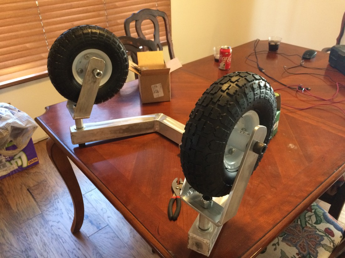
I used 5/8-11 screws for all the connections in the front caster assembly. I wanted to standardize on one size so I could buy several of one type of lock nut. Unfortunately the width of a 5/8-11 lock nut is 0.9375in and I don’t have a wrench that size. I also don’t have a hex wrench for the socket head cap screws either. The picture above shows everything hand tightened. I’ll have to go pick up the right tools to get this all put together.
More to come soon!

Update: a 5/16-18 bolt with several 5/16-18 hex nuts on it makes a fine little “hex key”. The flats on the bolt are 0.5in across and will fit nicely in the socket of a 5/8-11 screw. Drop a 1/2 wrench on the nut and tighten things down. I think this will also work to unscrew things as long as you don’t put the 1/2 wrench on the last hex nut on the bolt (obviously). I used a larger wrench on the 1/2 wrench to get some extra leverage. It worked out pretty nicely, and didn’t cost a dime!
LikeLike