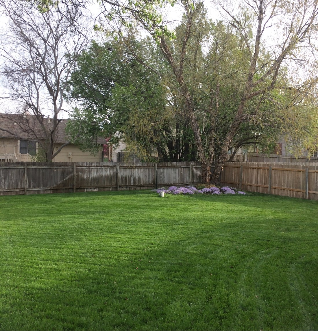
It’s been a while since I’ve posted, but that doesn’t mean I haven’t been busy. The back yard is starting to really green up and I think the worst of the cold is finally behind us here in Kansas.
I purchased a replacement relay board for the one that went bad several of weeks ago. Unfortunately, I didn’t read the fine print and the new relay board requires you to ground the appropriate pin instead of applying 5V to it in order to trigger the relay.
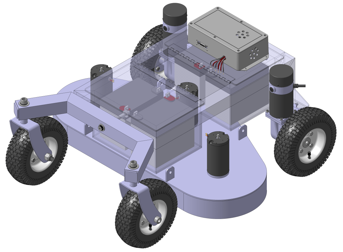
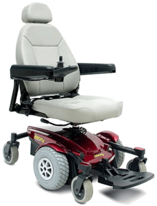
Since I’m now using a high current relay to switch the Sabertooth, I decided to resolder the damaged terminals on the relay board and put it back in the enclosure to switch the high current relay. I’ve taken the wheel chair robot out and tested it, and it is working quite well.
The RTK GPS system is working great, but unfortunately my backyard is still a very challenging environment to work in. Maintaining an RTK fix for 50% of the time is about all I can do. Because of this, I am exploring two different improvements to the wheel chair robot.
Optical Flow
For the uninitiated, optical flow is the concept that modern computer mice use to measure the motion of the mouse. An integrated circuit with a built in “camera” takes rapid (500Hz-ish) pictures. The pictures are very low resolution, 16 bit grayscale or thereabouts, and really small, like 32 pixels square. Using math, the vector difference between each frame is computed, and if you know how far above the surface you are you can then estimate your translation.
The same concept can be applied to our robot wheelchair. Take a camera, point it at the ground, measure how far the camera is above the ground and voilà! With some creative coding, you can estimate your robot’s translation. Optical flow is great because it measures your vehicle’s absolution translation, not some intermediate measure like wheel turns or integrating accelerations to back into your position.
What’s really cool is the Ardupilot code already features optical flow! There’s only one catch… it’s currently only implemented for copter. So for the time being, I’m going to have to either bribe a genius on the internet to port the code to Ardurover, or I’ll have to do it myself. I’ve started playing with the Ardupilot code, but let’s be real. I have no clue what I’m doing.
Wheel Encoders
This is a feature that is already implemented in the Ardurover code. I’m thinking about buying some rotary optical encoders to leverage this feature. For ~$140 I can get two encoders and pretty much plug and play them into my motors.

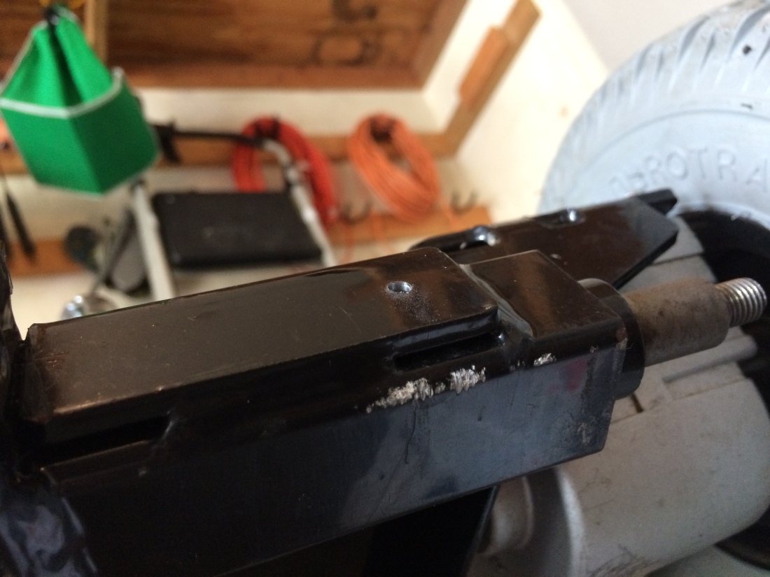
To properly implement them, I need to figure out the gear ratio on the gear box. I measured it by counting turns of the back shaft on the motor per one wheel rotation and came up with a ratio of 32:1. I thought this was an odd ratio (I was expecting 30:1 or 60:1) so I did some digging and it turns out there’s a little bit more going on in that box than I initially suspected.
To measure the gear ratio, I could just use the encoders and hook them up to an Arduino, measure several wheel rotations and then see how many pulses I get out of the encoder, so I’m not going to bust open the gearbox and start counting teeth. In theory though, this would be the correct way to determine the exact gear ratio.
Some things I’m not sure about:
- How much wheel slip is acceptable before the encoders actually start degrading position estimation instead of improving it? Wet grass isn’t nearly as friendly as concrete.
- How many pulses per revolution (PPR) do I realistically need? Not much is my guess, but if the Pixhawk can read them, the more the merrier. Where’s the sweet spot?
- The wheel encoders help if you can continue to get good absolute positioning information from the RTK GPS. But they’re only as good as your initial position, and you’ll quickly start experiencing drift once you lose your RTK fix. How long can the wheel encoders tide you over between RTK fixes?
For ~$140, I think I’ll take the risk and see how well they work.