A New Addition to the Mr. Mower Family

68993112_10157592162359312_6153332179632914432_n
The Mr. Mower family is growing! Timing both a lull in the Kansas wind with a smile on Mr. Mower Jr.’s face for a picture is quite challenging.

The lack of activity here on MowerProject.com hasn’t been due to a lack of autonomous lawn mower development. This June we were blessed with a baby boy, and he has been taking up a lot of our time! Posting to the blog in the meantime has been difficult.

Juggling my 8 to 5, the mower project, and making time for Mr. Mower Jr. has been quite challenging. I owe a special thanks to my wonderful wife for letting me run errands for the project and work on it in the evenings. She is truly something special! Having her to bounce ideas off of and to encourage me along the way has been invaluable. I love you so much Mrs. Mower!

As I’ve done in the past, I find it’s good to set goals. Even if I don’t achieve them, they focus my mind and give me a sense of accomplishment and purpose as I work toward them. Below are some goals I have for the next few months.

Finish Procurement and Begin Assembly

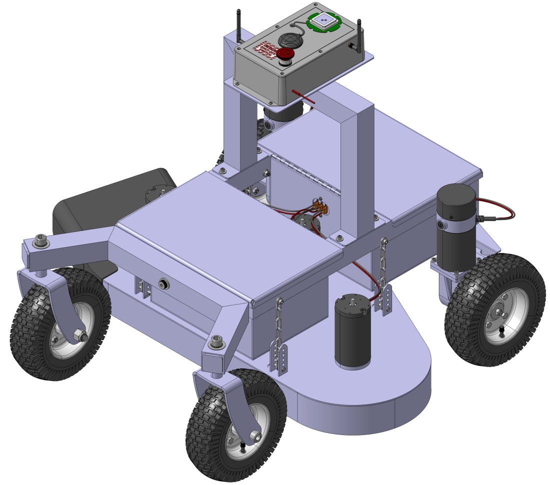
I have all of the parts to build the prototype robot lawn mower except for two more SLA batteries and new enclosures for the electronics. The SLA batteries are so cheap that I think it’s worth a gamble on them instead of ponying up the $1,000+ I’d need for some good quality LiFePo4’s.

Once those items arrive I will start to wire up the enclosures and get the subassemblies put together. I will probably need to make another wiring diagram showing how everything connects and functions before I get too far along.

Support Fabrication of the Prototype Weldments

Originally I had planned to fabricate a lot of the robot lawn mower components myself. The idea was that it would be cheaper to purchase my own tools and make the parts myself. Unfortunately, that plan requires a lot of time, a resource I’m very much short on these days with Mr. Mower Jr. in the picture. The economics of paying someone to make the parts suddenly looks attractive again.

To this end I’ve found a local gentleman who is helping me make the weldments. I find myself over at his shop every week or so answering questions about the design, and working with him has been very productive. His feedback has been quite helpful in helping simplify and refine the design so that it is easy to fabricate.

Functional Testing

I have a litany of questions I need to get answered about the performance of the prototype before we even cut grass. A few questions I need to get answered:

  1. How long can the mower run on four 12V, 35Ah SLA batteries?
  2. How well does the prototype handle pivot turns?
  3. How much current does the entire robot draw at typical operation?
  4. We need to verify emergency stop and safety features function correctly.
  5. How much air flow does the current mower deck and blade design create?

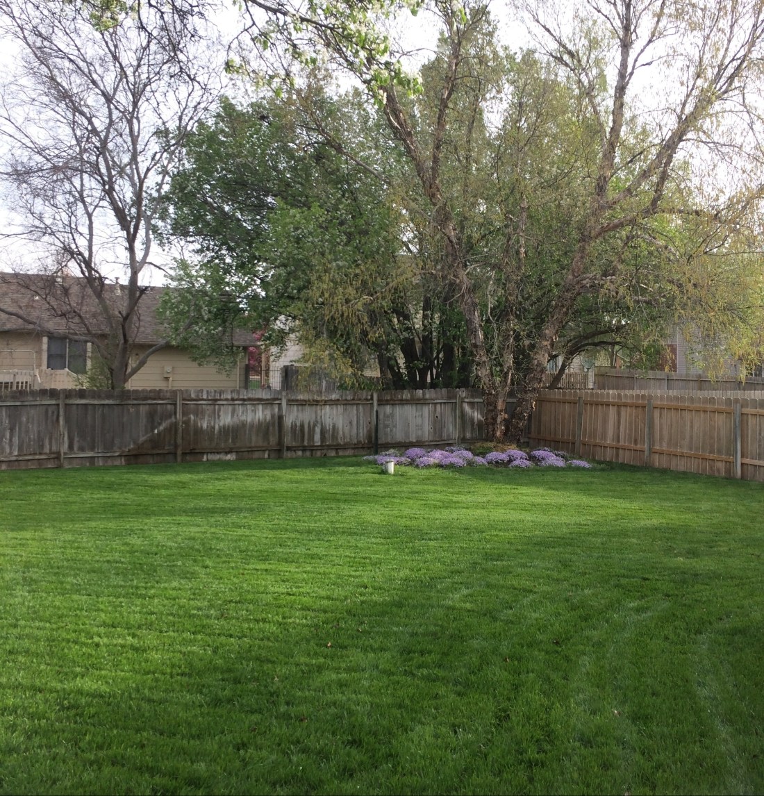
Once I’m satisfied the design adequately answers these questions, we can start cutting grass. Stay tuned for some pictures of the fabrication so far!

Making New Things is Hard

Paul Breed has a post that resonates with me over at his blog Unreasonable Rocket:

“Making a new thing is hard. You will fail, over and over again, you will fail.
Edison tried thousands of light bulb filaments before he found one that worked.”

-Paul Breed

Paul knows this much better than I do. He’s had rockets blow up on the launch pad that he spent several months and several thousand dollars making.

I’m a tightwad, and I’m also not a risk taker. The combination of those two traits has led to some frustration lately as I try to find a way to fabricate the robot lawn mower.

The tightwad in me says find the cheapest way to do it, even if the trade off is more of my time and frustration. I don’t need a drill press. I’ve got a perfectly good cordless drill! That’s the mentality, anyway.

Because I’m not a risk taker, I spend a lot of time planning in my CAD software. You can prevent a lot of issues by planning well. To see the flip side of this coin, search the internet for “DIY robot lawn mower”. Most of the results you get are… janky, to say the least.

Because of these two traits, my initial plan was to have someone else make the robot lawn mower for me. I’m an engineer, not a machinist or welder. I was willing to spend about $2,000 dollars to have someone make my weldments complete. I can do the final assembly work myself; I have hex keys and wrenches at home.

Unfortunately, very few weld shops are willing to do anything but weld for me. They want you to bring them parts, and they’ll weld them up. The ones that are full up fab shops aren’t too interested in my work right now. A few of them have talked to me, but their quotes were several thousand dollars for just the mower deck. I’d hate to see their quotes for the chassis weldment.

For the cost these folks quoted me, I can go get my own band saw, drill press, slip roll machine, and various other tools to make my parts, and come out way ahead. There are lots of guys that can weld aluminum out there. They just don’t want to go buy material, cut it, make it per your print, etc. They’re welders, not prototype makers.

So based on the astronomical quotes I’ve received I’m going to go purchase my own tools, and start fabricating the parts I need for the robot lawn mower. I’ve done a good job making sure I can actually make each part I’ve designed. Now I just need to shell out some money for some good tools, and make it happen.

On my shortlist of items to buy:

tooling
The tools I’ll need to make all the parts for the prototype robot lawn mower.

Having my own tools will be nice. I’ll finally be able to control my own destiny, and make exactly what I need.

Spring is Here!

It’s been a while since I’ve posted, but that doesn’t mean I haven’t been busy. The back yard is starting to really green up and I think the worst of the cold is finally behind us here in Kansas.

IMG_4337
The backyard on this fine spring morning. Winter is finally over!

I purchased a replacement relay board for the one that went bad several of weeks ago. Unfortunately, I didn’t read the fine print and the new relay board requires you to ground the appropriate pin instead of applying 5V to it in order to trigger the relay.

Since I’m now using a high current relay to switch the Sabertooth, I decided to resolder the damaged terminals on the relay board and put it back in the enclosure to switch the high current relay. I’ve taken the wheel chair robot out and tested it, and it is working quite well.

The RTK GPS system is working great, but unfortunately my backyard is still a very challenging environment to work in. Maintaining an RTK fix for 50% of the time is about all I can do. Because of this, I am exploring two different improvements to the wheel chair robot.

Optical Flow

For the uninitiated, optical flow is the concept that modern computer mice use to measure the motion of the mouse. An integrated circuit with a built in “camera” takes rapid (500Hz-ish) pictures. The pictures are very low resolution, 16 bit grayscale or thereabouts, and really small, like 32 pixels square. Using math, the vector difference between each frame is computed, and if you know how far above the surface you are you can then estimate your translation.

The same concept can be applied to our robot wheelchair. Take a camera, point it at the ground, measure how far the camera is above the ground and voilà! With some creative coding, you can estimate your robot’s translation. Optical flow is great because it measures your vehicle’s absolution translation, not some intermediate measure like wheel turns or integrating accelerations to back into your position.

What’s really cool is the Ardupilot code already features optical flow! There’s only one catch… it’s currently only implemented for copter. So for the time being, I’m going to have to either bribe a genius on the internet to port the code to Ardurover, or I’ll have to do it myself. I’ve started playing with the Ardupilot code, but let’s be real. I have no clue what I’m doing.

Wheel Encoders

This is a feature that is already implemented in the Ardurover code. I’m thinking about buying some rotary optical encoders to leverage this feature. For ~$140 I can get two encoders and pretty much plug and play them into my motors.

encoder on motor
The wheel encoders mounted where the brake used to be on the motor. Fits like a mitten!

To properly implement them, I need to figure out the gear ratio on the gear box. I measured it by counting turns of the back shaft on the motor per one wheel rotation and came up with a ratio of  32:1. I thought this was an odd ratio (I was expecting 30:1 or 60:1) so I did some digging and it turns out there’s a little bit more going on in that box than I initially suspected.

To measure the gear ratio, I could just use the encoders and hook them up to an Arduino, measure several wheel rotations and then see how many pulses I get out of the encoder, so I’m not going to bust open the gearbox and start counting teeth. In theory though, this would be the correct way to determine the exact gear ratio.

Some things I’m not sure about:

  1. How much wheel slip is acceptable before the encoders actually start degrading position estimation instead of improving it? Wet grass isn’t nearly as friendly as concrete.
  2. How many pulses per revolution (PPR) do I realistically need? Not much is my guess, but if the Pixhawk can read them, the more the merrier. Where’s the sweet spot?
  3. The wheel encoders help if you can continue to get good absolute positioning information from the RTK GPS. But they’re only as good as your initial position, and you’ll quickly start experiencing drift once you lose your RTK fix. How long can the wheel encoders tide you over between RTK fixes?

For ~$140, I think I’ll take the risk and see how well they work.

Weather

Weather in Kansas during February can be pretty awful, and this year is no exception. We’ve had a lot of snow lately, and the temperatures have been 30’s or lower on the days that I could take the robot wheelchair out for some more testing.

A few months ago I listed some goals I had for the robot mower prototype. I’ve made progress toward some, and overall I feel pretty good about where I’m at for now. Here’s an update of the progress.

Prototype Robot Mower Design

robot-mower-03-03-19.png
The robot mower design as of this evening.

The robot mower design is about 70% finished. I am working on getting the wires modeled in my CAD software currently, and this has been time consuming but I know it will pay off down the road.

I need to revisit how I’m attaching the mower blade to the motor shaft. I had considered using some cheap QD pulley bushings because they have a nice keyway in them that matches the motor shaft and holes that would mount easily to the blade, but I’m not sure this is the best way to do things.

I wish I could find these bushings without the split in them. I’m not sure they make them that way. The split makes me worry that it will be difficult to get good clamping force around the shaft. Also, nothing but a set screw keeps the key and bushing clamped up against the shaft. Because the motor is mounted vertically, all heck could break loose if the set screw loosens up. The bushing could conceivably slide off the shaft while spinning at stupid high RPMs. Not good.

At any rate, CAD work is about the only thing I can work on when there’s 4 inches of snow on the ground outside.

Sourcing Weldments

I’ve been very disappointed with some of the local weld shops I’ve sent drawings to for quote. I live in an industrial town and there are lots of mom and pop shops that I figured would jump at the chance to pick up a small job like mine. I’ve received 5 no bid quotes so far, and haven’t heard back from 3 other shops. Very frustrating.

I tried one of those online weld shops and they quoted the mower deck at $4,500. That’s definitely not in the budget, and I know this weldment is worth no more than several hundred dollars. If you can weld 0.125in thick aluminum sheet metal, leave a comment and I’ll send you over some drawings and maybe we can make a deal.

Purchased Parts

I’ve purchased one of the E30-400 motors to evaluate, but haven’t had time to play with it yet. It’s a lot smaller than I expected. I hope to do a write up on it here in the next few weeks.

I also purchased some high current automotive relays for switching power to the deck motors. The wheelchair design has all of the current running through a 20A switch which in hindsight is a really crappy design. It works for the wheel chair, but to power three 50A motors requires a better solution.

RTK GPS Integration

The Ardusimple RTK GPS boards are working far better than I expected. There’s really very little integration left to do. I will try to take the wheelchair robot out to a large parking lot here when the weather warms up to get a better idea of it’s performance in a decent GPS environment. I’m very excited to see how it does without a ton of trees and buildings around. Its performance so far has been pretty awesome.

Rebuilding the Wheel Chair Robot

I haven’t rebuilt the wheel chair robot yet in light of our crash a few weeks ago. This is also on my to do list. Hopefully we’ll have a chance to do that this next weekend. It’s really hard to get motivated work on a lawn mower robot when it’s 20 degrees outside and there’s snow on the ground.

New Goals

Because RTK GPS integration isn’t going to take nearly as long as I anticipated, I need to spend more effort on getting the robot constructed, under budget and by May if possible. I may try some weld shops in surrounding towns, or possibly the old Craigslist method where I just post drawings and see who replies.

Power Consumption

I decided to make the autonomous lawn mower fully electric for one big reason: If a person has to walk out to the mower with a gas can and refill the tank, is it really autonomous?

Ideally, you want the mower to do it’s job without any human intervention. If you have a gas engine, no matter how you cut it fuel has to be delivered to the mower in some fashion. With an electric design, you can have the mower automatically dock with a charging station when the battery gets low. No human required.

So from the get-go I have been trying hard to make the mower electric. I am encouraged by some electric riding mowers out there that use SLA batteries as their power supply. I like SLA batteries because they contain a lot of energy and are fairly cheap. Minimizing battery weight and volume isn’t a huge constraint for this project, thankfully.

Because these electric riding mowers cut grass and carry a ~200lb person on the mower, I have been operating under the assumption that as long as our batteries are larger capacity than those on this riding mower, we should be okay. That Ryobi mower features a battery bank that consists of four 12V, 25Ah SLA batteries.

I am beginning to question that assumption…

Power Consumption

Sizing the batteries ultimately depends on how much power the mower needs. The deck motors take the lion’s share of power consumption. Previously I estimated the mower would require motors that can output at least 5ft-lbf of torque to cut through thick grass based on typical gas engine torque output.

Examining the torque curves for the E30-400 motor I selected for our design shows that at 5ft-lbf or 3.7N-m torque, the motor consumes 1400W of power. If you assume all three motors pull this level of power, the deck motors collectively consume 4200W.

The drive I’m using on the mower design are stolen from the wheel chair. I suspect they are rated for 500W but I am not sure. The gearbox on them ensures they will generally be operating in an efficient area of their torque curves, so I am going to consume both motors consume 250W, and collectively consume 500W between the two motors.

The control electronics are almost negligible compared to the power consumed by the motors, but I will budget 100W for all the other little things on the mower, just to be safe.

That brings the total estimated power the mower needs during operation to 4200W + 500W + 100W = 4800W.

Battery Capacity

The batteries I’ve selected are four 12V, 35Ah SLA batteries. If you assume we intend to discharge these batteries 100% (and that doing so was physically possible), you could obtain (4)(12V)(35Ah) = 1680Wh of energy. If we were to draw 4800W of energy from these batteries, we would drain them in (1680Wh)/(4800W) = 21 minutes. Yikes.

But it gets worse. Because we’re pulling so much power out of these batteries, it looks like you have to discount the total amount of energy you can get out of them. I’m not entirely sure what that calculation looks like, but from the SP12-35 datasheet, it looks like a 1hr discharge rate only allows you to get 21.8Ah of charge out of each battery. That’s only 60% of the 20hr rate of 35Ah. I could be wrong about this interpretation of the datasheet, please correct me if I am mistaken.

Some Thoughts

Do the motors really draw that much power? Holy moly I hope not. At their most efficient, the motors draw 500W of power. Running the calculations above with this number gives you a run time of 48 minutes. Still not great.

The reality is somewhere between those two extremes. Taking the average of the two gives 35 minutes of run time. I was hoping for something more in the neighborhood of 2 or 3 hours. Going up to some 12V, 50Ah batteries could give us some extra oomph, but I don’t think it will be 3 hours of oomph.

Please let me know if these numbers seem way off base, it’s my best swag at them I can come up with. The last thing I want is a mower that can only cut grass for 10 minutes.


Project Goals

Here are my goals for the robot mower over the next few months. I need to plan and execute well so that the mower will be ready to cut grass this spring.

December

Finish designing the robot mower, including wiring and planned integration of the RTK GPS module. The module should arrive at the end of December. I promise I will post more about the RTK GPS module soon.

January

Send the robot mower weldments out for quote. I’ll also start sourcing purchased parts for the project. Any design changes based on vendor feedback will be incorporated during January. I’ll also start playing with the RTK GPS module, getting a feel for performance and how to configure the base station.

February

Select a vendor to build the weldment. Start receiving in purchased parts. Implement the RTK GPS module on the wheel chair robot and take it out for field testing. If the weldments are completed in February, we’ll start assembling the robot mower.

March

Finish construction of the robot lawn mower. Conduct functional testing. Make any last minute changes to the design based on the testing results. Continue field testing the RTK GPS module on the wheel chair robot.

April

Integrate the RTK GPS module on the robot mower. Start working on making the mower truly autonomous, with my backyard as the test bed. It’s fully fenced in so it should be a safe area, and the trees and houses nearby provide a fairly challenging GPS environment, perfect for working out the kinks.

The Bottom Line

Shoot for the moon; even if you miss, you’ll end up among the stars.

-Some motivational kindergarten classroom poster

I realize this is a very aggressive schedule, but it’s been my experience that if you aim high but miss, you still will still achieve a lot more than you would have if you had set a more “realistic” goal. So we’ll see how far we get over the next few months.