If you think a good design is expensive, you should look at the cost of a bad design.
-Ralf Speth, CEO of Jaguar Land Rover
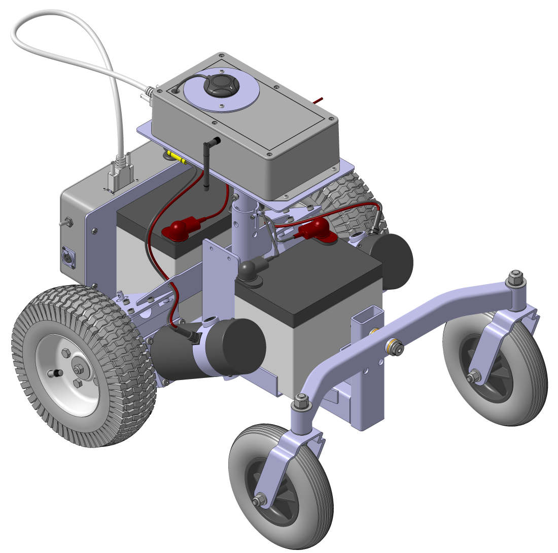
I know from experience that Mr. Speth is correct. So with a good functional understanding of my electrical components and a wiring diagram in hand, I set out to create a detailed CAD model of the wheelchair.
I do a lot of CAD modeling at my day job, and it’s something I really enjoy. But you don’t have to get anywhere near the level of detail shown below to start seeing real benefit from a CAD model.
CAD modeling is difficult and tedious if you’re doing it right. That’s because you will run into questions like these:
- How does that enclosure mount to the chassis?
- Where will I position that switch?
- Do those components fit in that small area?
- Can I route those wires through there?
- Is that plate rigid enough to hold that enclosure in place?
In a nutshell, CAD modeling forces you to plan. The more detailed your model, the more detailed your plan. You can choose to do your planning in the garage when you’re scotch taping your Pixhawk and GPS to a chunk of cardboard, or you can do your planning in a CAD program from your air conditioned kitchen while you sip an iced tea. I prefer iced tea.
CAD pro-tip: most stuff is already modeled up somewhere. You just need to know where to look. A good place to start is the manufacturer’s website. Search for the term “CAD model” or “STP file” with the part number after it. Almost everything on McMaster’s website has a CAD model you can download, too. Do some digging. You’ll be surprised what you find!
Reverse Engineering
Before I started drawing up the modifications I was going to make to the wheelchair, I spent a lot of time reverse engineering the existing structure. Would you buy new cabinets for your kitchen remodel before measuring your kitchen? Of course not, and modifying the wheelchair is no different. You’d measure things out to understand your constraints.
It’s important to know what you’re working with so you don’t accidentally put components that interfere with stuff on the wheelchair. But beyond constraints, having a good reverse engineered model also reveals possibilities. Unexpected places to bolt stuff suddenly pop out at you. Places to run wires begin look obvious.
If you don’t have a good set of calipers you need to get some, this will make reverse engineering your existing structure a lot easier. The more accurate your CAD model, the more value it will have. Measuring the ID of a hole with a tape measure just doesn’t work that well.
Another cool side effect of reverse engineering something is the learning aspect. Some engineers out at Pride Mobility probably spent a few months hashing this wheelchair design out. I know they put a lot of thought into it. I can learn a thing or two from how it’s built and why it has the parts and features on it that are there.
Hopefully I’ve sold you on the importance of laying things out. Spend several hours thinking about your robot and drawing things out, even if it’s on a dirty paper towel. The alternative is ugly.
A More Robust Robot
No more cardboard. I found these pretty inexpensive enclosures that were the right size for this project. You’ll have to purchase a separate mounting panel if you want something to attach your parts to, which I did. As an added bonus, Polycase provides CAD files of their products on their website.
I mentioned previously that I suspected there was a lot of magnetic interference coming from my motors that was affecting my compass. To try and mitigate that, I decided to segregate all of my power electronics from my control electronics.
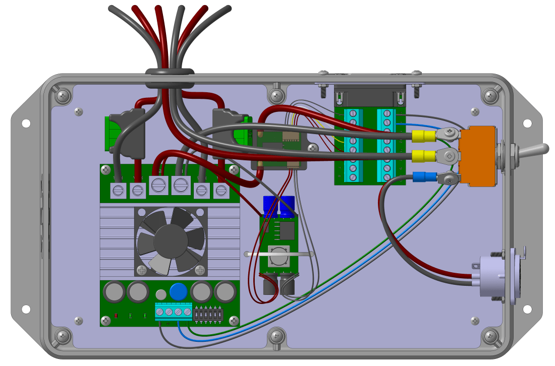
The control enclosure is intentionally oversized for the components it houses. Eventually I may insert some kind of companion computer and RTK GPS unit. Or maybe a camera. Who knows? But at least with extra space, I’ll have options.

Connecting the Enclosures
Connecting the two enclosures posed some surprising challenges. Power to the Pixhawk and other control electronics comes from the BEC, which is in the power electronics enclosure. But the control signal for the Sabertooth comes from the Pixhawk. All in all I needed to run 9 wires minimum between the two enclosures.
I spent way too much time researching connectors and wire assemblies, trying to find a cost effective solution. I bought 100ft of phone cable at a garage sale for $2 and initially intended to use that, but how do you connect your wires once they’ve been fed back into your enclosure?
I wanted to avoid crimping my own custom cables because it requires some expensive, specialized tools that I would use once, maybe twice. I also wanted a solution that was plug and play, to allow me to modify things on the go or add additional wires down the road. So soldering was out.
I also had to contend with signal loss through the cables. You can only run a 26 gage wire so far before you start getting noticeable losses. You can double up on small wires to mitigate that effect, but that’s not a proper solution in my opinion. So in summary, my constraints were:
- No crimping or soldering
- Flexibility for changes in the future
- No major signal loss through the cable
- One cable between the enclosures
- Robust and secure construction
During my research I stumbled upon these D sub connector breakout boards made by Winford Engineering. They even had a CAD model on their website. If you pair these connectors with a cable that is made of something bigger than 26 gage wire you’ve got a pretty good solution, I think. Spend $5 on an old DB15 or DB25 cable at the goodwill, and another $20 for a pair of those D sub connector breakout boards and you’ve satisfied all of those constraints.

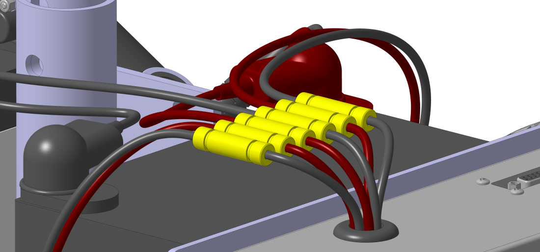
- The male DB15 breakout board. The jack screws clamp the breakout board to the adapter plate, and the adapter plate screws into the enclosure wall.
There were a few drawbacks to this solution though. I had to make a custom adapter plate to mount the D sub connectors to the enclosure. And the smallest DB15 cable I could find was still 2ft long. Not great, but they don’t make them in 10in lengths off the shelf. And as I mentioned, I’m not too excited to get into the custom cable making business.

I initially intended to make the adapter plate out of aluminum, but looking around it might be just as cheap to 3D print it. The numbers I get back from some quotes I have out will determine what I decide. That interior profile with a +/- 0.020in tolerance is going to be expensive to machine.
Mounting the Enclosures
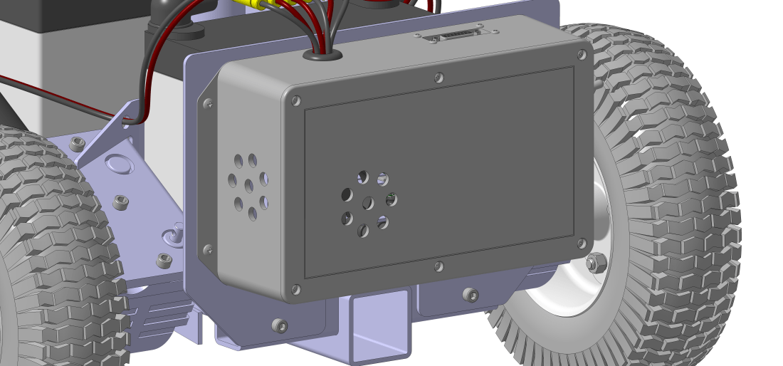
To mount the power enclosure, I had a small aluminum plate cut. The enclosure is attached to the plate and the plate is attached to the wheelchair base.
I’m trying use something other than steel for material wherever I can to prevent further compass issues. Even absent the compass problems though, steel is difficult to cut through. Unless the rigidity is required it’s probably worth it to use aluminum if you can.
The Sabertooth 2X60 comes with a cooling fan and a nice heat sink. I’ve set up the power enclosure to take advantage of this feature by drilling holes in the enclosure to allow the fan to pull air through it. I also selected the grey colored enclosure instead of the black to try and keep heat retention to a minimum. If you’ve ever owned a black car in the summer time, you’ll know why.
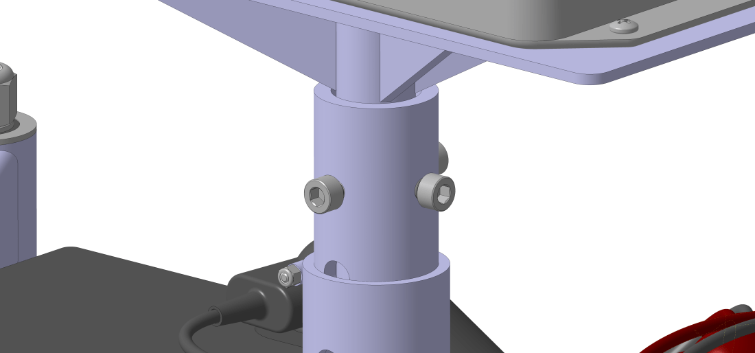
To mount the control enclosure, I made a small pedestal weldment that functions like the seat did before I removed it. This allows me to adjust the height of the enclosure if I need to move it further away from the motors. The enclosure bolts to the weldment the same way the power enclosure does.
Connecting the Motors and Batteries
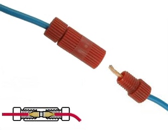 To connect the batteries and motors to the power enclosure, I found these interesting connectors called Posi-Locks. They allow you to both electrically and mechanically connect your wires. Strip the wires, cram them, and cinch them down. They aren’t cheap, but they are reusable.
We’ll see how well they work once I start putting things together. I’m using six 10 gage Posi-Locks for connecting the two motors and B+ and B- battery terminals to the Sabertooth 2X60.
Someday I hope to actually build a robot lawn mower. I’ve tried to design everything here in a modular fashion so I can take this equipment over to the new robot without too much hassle when that day comes.
