I was able to test the wheel encoders on the wheelchair robot the other night. I had mixed success. The rpm1 and rpm2 status values in mission planner were all over the place. But they were consistently the same magnitude positive or negative:

So something is not right. Talking with the folks on the Ardupilot forum it sounds like I selected an encoder that has too much resolution for the speeds I’m running the motors at.
So to make sure I’ve selected the correct encoders (or to determine which encoders I should have selected) I need to do some math. The encoder I purchased is an E5-900-394-NE-S-H-T-3. It’s rated for 900 counts per revolution of the encoder (CPR).
Maximum Encoder RPM
Encoders have a maximum speed at which they can spin and still accurately measure angular rotation. Per page 4 of the E5 datasheet, an E5 encoder rated for 900CPR can spin at a maximum speed of 20,000RPM.
The encoder is attached to the motor armature shaft, which is in turn connected to a 32:1 gear box. So based on this maximum encoder speed and gear ratio, the fastest corresponding tire rotation speed is:
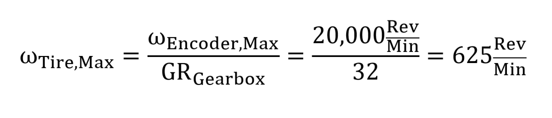
Connected to a small 12V battery, the tire rotation speed was about 60RPM. Doubling that on the wheel chair robot (it has a 24V power supply) is still well below this maximum speed.
So I am confident the encoder can report rotation measurements accurately. Now whether or not the Pixhawk can read them at the speed it reports them is another story altogether…
Frequency of Pulses
How fast is the encoder sending pulses? Let’s say that the tire on the gear motor rotates at 150RPM. Because it’s a quadrature encoder, you get four pulses for every count. The frequency of pulses is then:

That’s a lot. It’s one every 3.47 microseconds. Can the Pixhawk handle that? I’m not sure.
Resolution
What distance does the robot travel per encoder count? The diameter of the tire is 10in:
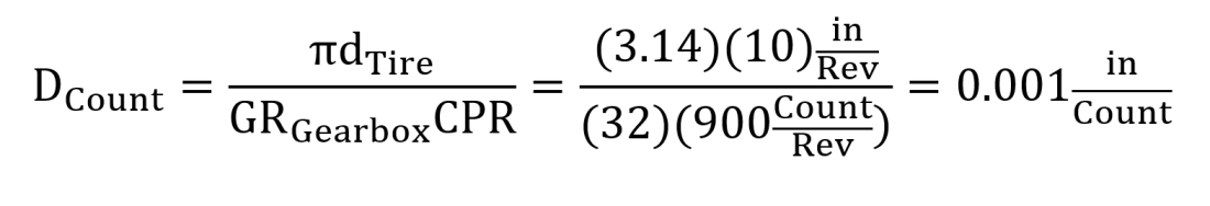
That’s a ton of resolution. Way more than we realistically need. Something in the neighborhood of 0.03in/count is more reasonable.
Pull Up Resistor
Another tip I got from the Ardupilot forum was to use two 10kΩ pull up resistors between the A and B signal pins and the Vcc pin on the encoder. I tried that last night without much success. I also tried to pull the A and B signal pins down to ground, but that didn’t work either. I tried it on the left encoder but not the right to see what the difference would be. The numbers were still all over the place, but they were now slightly different. So there’s that.
Going Forward
I am going to purchase an encoder with 32CPR, which results in 1024 counts per tire revolution, and a resolution of 0.031in/count. Hopefully this will be compatible with the Pixhawk. If the 32CPR encoder still doesn’t work, at least I’ll know the issue is something else.
