I was able to take the prototype robot lawn mower out for a drive this week. Watching the design drive off the computer screen and into my backyard has been immensely satisfying. Below are my notes from a day spent becoming better acquainted with the robot mower.
Vehicle Handling
Initially I wired the RC receiver straight into the Sabertooth so I could take it out for a drive. I’d forgotten how much smoothing the Ardupilot software adds to the control output. The robot was almost too responsive without it.
But overall, it handled wonderfully. I was almost able to drive up the curb from my street into my yard, but there wasn’t enough traction to get the back wheels up the curb. So far, so good!
However…
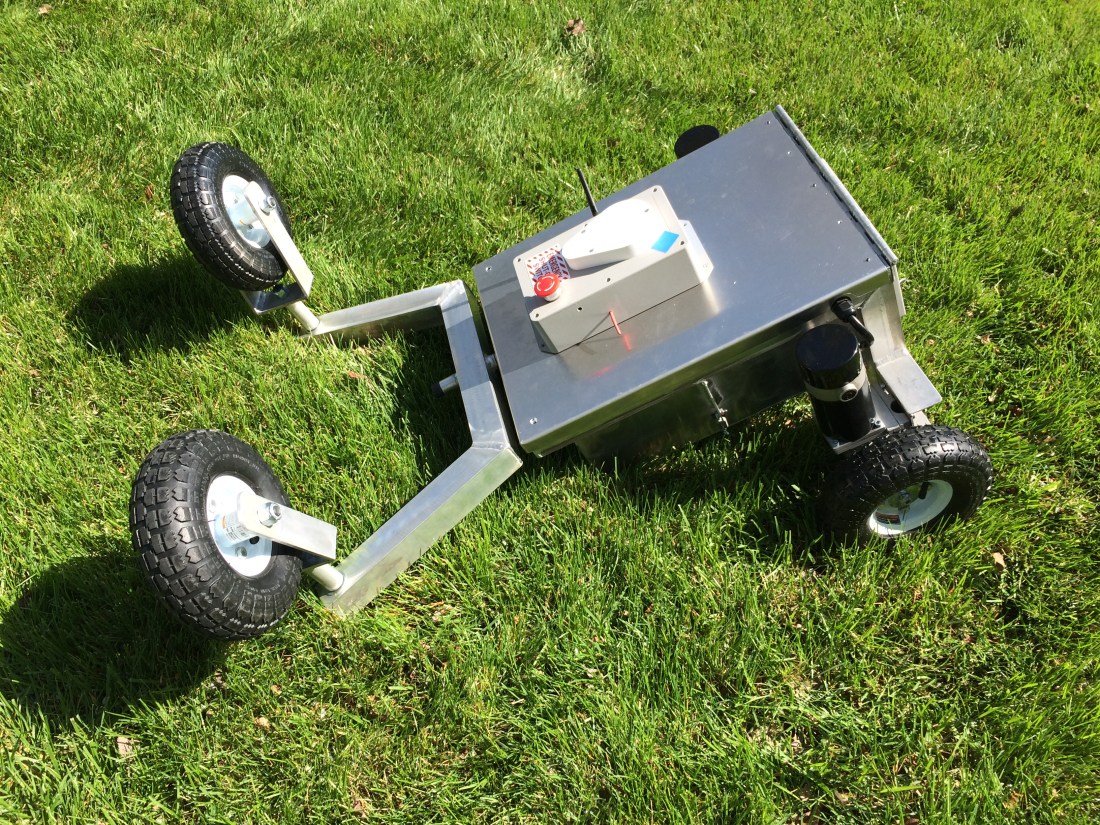
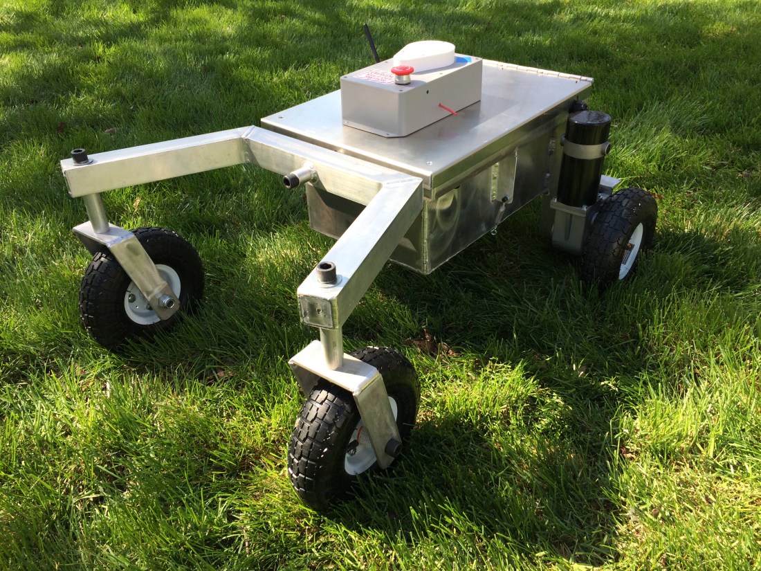
After I got the Pixhawk wired up (more on that below) I ran a few autonomous missions and started tuning the steering and throttle PID values. At lower steering turn rates, I noticed the swivel caster wheels sometimes catch on the grass instead of swiveling, and the whole setup actually rotates about the center pin. The scenario in the picture above only occurred once, but I noticed the wheels getting hung up more than once.
When I was putting the robot together, I noticed the casters weren’t fabricated per my print. I had designed them with more offset between the wheel axle and the swivel axis. If this continues to be a problem, I’ll have them remade with a little extra offset so they swivel easier.
Wires
Getting the robot wired correctly was nerve wracking. I made a wiring diagram for the power enclosure and modeled up all the components and connections to make sure they fit, but I skipped this planning step for the Pixhawk enclosure. The amount of wires I had to route to the Pixhawk multiplied quickly:
- 5 wires from the drive wheel rotary encoders, a total of 10 for both motors.
- 4 Sabertooth control wires.
- 4 relay control wires.
- 6 wires for the Pixhawk power port.
- 2 emergency stop wires.
- 2 additional wires to power the servo rail on the Pixhawk.
I wasn’t expecting 23 wires needing to be routed to the Pixhawk enclosure, and making sure I didn’t get something wired incorrectly was nerve wracking.
And ultimately, I did wire something incorrectly. When I first powered the robot on, nothing happened, other than the Mauch BEC getting hot. And that’s never a good sign.
Turns out I had incorrectly wired the servo rail by swapping the + and – wires. Yikes. I eventually discovered the issue and fixed it, but not before learning a lot about the LM2576 voltage regulator I incorrectly thought was the issue.
Wheel Encoders
After I fixed the wiring, everything seemed to work, until I started running autonomous missions and had trouble getting the MAVLink Inspector within Mission Planner to show wheel encoder data. Initially I couldn’t even find the wheel encoder message. But after a few reboots it magically appeared. Not sure why it wasn’t visible from the start.
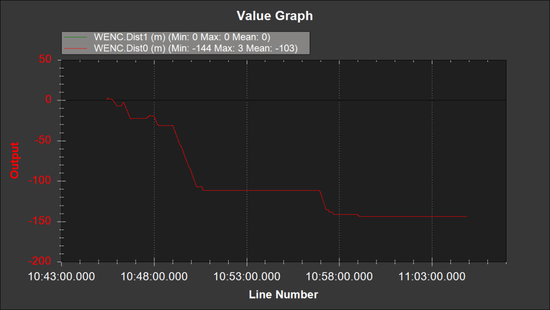
From the get-go, only the right wheel encoder was working. Below is WENC.Dist0 for the encoder on the left motor and WENC.Dist1 for the encoder on the right motor.
And below is what the graph for the right encoder by itself, WENC.Dist1 versus time, looks like.

So to troubleshoot, I swapped the encoders. The idea is that WENC.Dist0 should look like the graph above and WENC.Dist1 should look like more like the first graph, with values much greater than 10E-6 and gradually increasing. This would isolate the issue to the encoder and not a settings, wiring, or Pixhawk error.
As an aside, having posted that graph I’m now wondering if the negative value means I have the A and B wires swapped. I was driving the robot forward mostly, so I would expect the values to be increasing, not decreasing. Regardless, at least the left encoder is obviously outputting some kind of useful data.
After swapping the encoders…
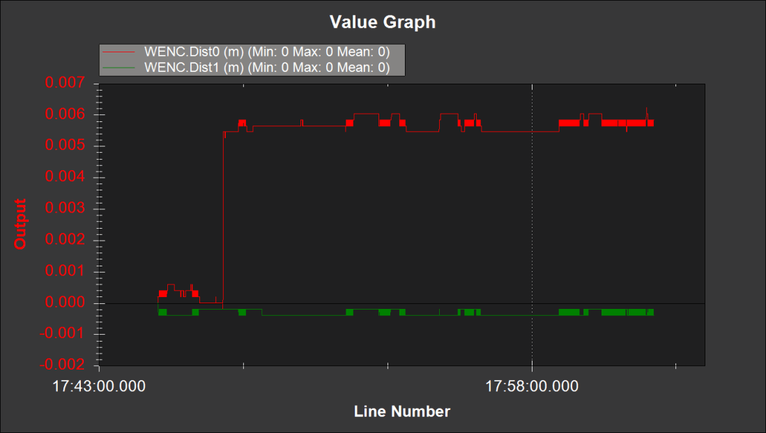
Great, now they’re both broken!
I decided to call it quits after this because the sun was going down. I took the robot back into the garage and got the Arduino out to see what it said about the encoder output. Unfortunately it confirmed that the left encoder at a minimum was broken. The Arduino sketch counted pulses and only got up to 1 or 2 regardless of how much the wheel was rotating.
I remembered I had some 900CPR encoders I had purchased a while back and decided to see if I could get them to work with the Pixhawk. So I swapped the 32 CPR encoder with the 900 CPR encoder, and lo and behold, it started to work again.
All I can gather is that I must have fried one or both of the encoders with my wiring shenanigans. But it concerns me that one of the encoders was working at the start of the day and stopped working by the end of the day.
More to come once I get the mower deck assembled and installed. You can find a brief video of the rover doing an autonomous mission in my backyard here.

Hello Drew!
I first want to start with a thank you. I had been following Wayne (Roby) on Deep South Robotics for the past year while working through my final semester at college getting my ME degree (glad to see there are other MEs getting their feet wet in the software and electrical side of the house!) While he had stopped posting, I found your blog which really suits the end state I was going for in my design.
I have my BOM for the items I am gradually purchasing (already have the wheelchair motors and gearbox,) but I was wondering if you had any wiring diagrams you would mind sharing with me? I have no experience with how everything integrates besides trying to follow along some youtube videos, but if you had a rough wiring diagram, it would definitely help me get a better big picture view of how each component talks to the next. If not, I have no problem giving it the ole college try and going through a few fuses 😉
Thank you!
LikeLike
Hi David,
Thanks for dropping by! I’m going to be honest, I never actually got around to making a proper wiring diagram for everything. I do have some back of the envelope drawings (literally, All State REALLY wants my business back and they send me lots of junk mail to scribble on), but nothing formal.
I divided my electronics into two enclosures: one for control and one for power distribution. My flight controller, radios, GNSS modules, etc. are on top of the robot, and my motor controller, relays, and BEC are in an enclosure on the back. I have several cable runs between the two boxes, 5V power going to the control enclosure, and signal wires going to my Sabertooth and relay boards in the power distribution enclosure.
I had to sit down for a few hours and draw a box with every pin or connector on each component and then draw lines between each one to really visualize it. I got to a point where I understood how each component interacted with the others and at that point I knew everything I needed to, and stopped drawing.
I’m not sure that’s helpful for you, but that’s how I approached it. You basically need to understand your components inside and out, and once you’ve done that everything becomes pretty clear, at least for me.
LikeLike