Running the wheelchair robot in autonomous mode has been a lot of fun. Seeing it come back to waypoints pretty much dead nuts to the same spot is very satisfying. So I’ve become a little complacent with keeping my hand on the “manual mode” button in mission planner in case the robot veers off toward something it shouldn’t.
And boy did I pay for it today. Remember that sprinkler well in my backyard? Well the robot seemed to remember it too, and I may be buying a new power switch for it this spring. I took my eyes off the robot for just a few seconds and boom, collision.
The rover V2 running to waypoints autonomously.
Normally this wouldn’t be too frustrating except for the fact that now the left motor doesn’t rotate at all. The right motor though still runs perfectly.
So I start to troubleshoot the problem using the following process:
I made sure the motor still works. I connected the motor wires to the battery terminals and it spooled up just fine. No problem.
I checked continuity across the motor wires to the relays and Sabertooth motor controller. Everything is connected. No problem.
I checked the relays to make sure they weren’t broken, they function as desired. No problem.
I checked the fuses on the motors. Not blown. No problem.
I swap the S1 and S2 wires on the Sabertooth, thinking this would eliminate the Sabertooth as the issue if the left motor suddenly worked and the right motor didn’t. No change, the right motor still responds to RC input, although in a funky way because S1 and S2 are switched. The left motor is still unresponsive. Might be the Sabertooth.
I removed the Pixhawk from the equation by hooking the Sabertooth up to RC input from the receiver directly. Same results, left motor still unresponsive, right motor works.
I also checked continuity across the DB15 cable between enclosures. Everything seems to be connected. No problem.
So from my cursory testing, the Sabertooth seems to have been bricked, at least on the left motor side. So I pull it from the enclosure and take it inside for bench testing.
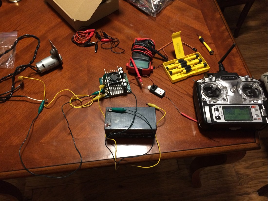
The bench setup for checking the Sabertooth. The battery and motor come from an old cordless weed eater. Very handy for this sort of thing.
But after some simple testing, both left and right motor outputs work when hooked up! So what could the issue be?
I’m thinking something got knocked loose during the collision. Nothing else makes sense. I’ll take everything apart and rebuild it just to make sure, but the lack of a smoking gun is somewhat worrisome.
The weather the past two weekends has been good enough to take the robot out for some testing with the new RTK GPS system. The Ardusimple boards are pretty awesome. The things I like about them:
It is plug and play with the Pixhawk (mostly).
It is configured to automatically survey in the base location. This means you don’t have to mess with U-Center and configure it out of the box, unless you want to plug in specific coordinates.
The long range radios I ordered mean you don’t have to mess with injecting the RTCM data stream through telemetry, although I will eventually attempt this.
Those things I like are huge. A few minor things I didn’t like:
The connector on the board is technically the correct Pixhawk connector, a JST-GH 6 pin connector. Which is great, but every Pixhawk I’ve seen has DF13 connectors. So I had to buy an adapter cable.
And then I had to mod the adapter cable because apparently the pinouts are inverted between the DF13 and JST-GH connectors. Frustrating.
The antenna choices offered by Ardusimple included a nice IP65 antenna and a unenclosed one. Initially I wanted the IP65 antenna, but then realized it came with a 5m (!) long cable. Where are you supposed to store 15ft of wire on a robot like this? So I went with the unenclosed version with a 10cm long cable.
The robot wheelchair with the RTK GNSS antenna mounted to the top enclosure. The second longer antenna is for RTCM corrections from the base station.
Once you tweak the adapter cable, you can plug it in to your Pixhawk and get RTK positioning in no time flat! Very awesome. No need to even tweak anything in mission planner. It will interpret RTK float and RTK fixed messages from the rover module.
To set up a base station, I grabbed my charcoal grill, a micro USB DC adapter, and an extension cord.
The base station is on the grill. The thought was the metal shell would make a good ground plane to mitigate multipath.
And it worked pretty well until the rover tried to ram it in auto mode. Not cool, robot wheelchair. Not cool.
Another issue is that my backyard is a crappy GPS environment. It was pretty easy to get an RTK fix when stationary, but in motion losing one or two satellites was enough to bump back to RTK float. Bummer!
So to fix these two issues I moved the base station to my front yard which had a better view of the sky, and mounted the unit on the roof of my car, which I’ve heard makes an excellent ground plane. Whoever said that is right.
This was quite an improvement. I was able to run autonomous missions while maintaining an RTK fix for 80%+ of the time in the back yard.
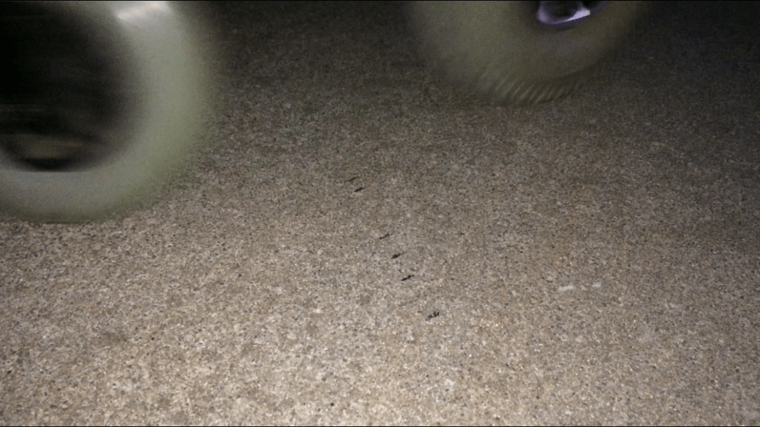
The black tick marks is the position of the front caster as it runs a loop in my driveway.
I had the robot run an autonomous mission in circles in my driveway and the repeatability was still pretty good. The tick marks on the drive way indicate the position of the side of the front caster through each pass. The distance between the furthest two tick marks is 5in.
Overall, the Ardusimple boards are looking like a very good investment.
As Roby over at Deep South Robotics can tell you, there is a lot of snake oil being peddled in the RTK GPS space. I’ve been a quiet spectator in this area for as long as I’ve been working on the mower project, and I’ve seen a lot of systems come and go.
Two modules that I had my eye on for a long time were SwiftNav’s Piksi V1 and Emlid’s Reach. Both were L1 only systems. I religiously visited their forums and poured over commenter’s experiences with both modules. In a nutshell, here’s what I learned:
L1 only systems can take a long time to get an RTK fix, and they can lose them in a heartbeat
If you’re in the air with a quadcopter or fixed wing plane, an L1 system generally works well because there is no multipath
If you have any kind of multipath that you are contending with, you are absolutely screwed with an L1 system
On top of that, integrating these systems require that master’s degree in computer engineering I talked about earlier (remember, I am a lowly mechanical engineer, wires aren’t really my thing). Neither system is truly plug and play, from what I can tell. A lot of the integration has to do with injecting GPS corrections through telemetry over MAVLink, as I understand it.
Then last year I discovered that u-Blox was coming out with their own L1 system, the NEO-M8P. I watched a very thorough introduction to the module and was almost going to buy one when I noticed that u-Blox was coming out with a multi-band, multi-constellation RTK GNSS receiver, the ZED-F9P.
I contacted the folks out at u-Blox and they said that an evaluation board would be available in Q1 of 2019, but in my research I stumbled across the folks at Ardusimple. These guys are making a similar evaluation board for the ZED-F9P module that includes a Pixhawk GPS port. Talk about simple.
Is this the holy grail of RTK GNSS? From my experience with this board so far, the answer is yes.
A Simple Test
I conducted a test similar to the one in the video I linked to above. I took reported baseline measurements from u-Blox’s u-Center software, converted the NED components to a net distance and then compared the value with a tape measure.
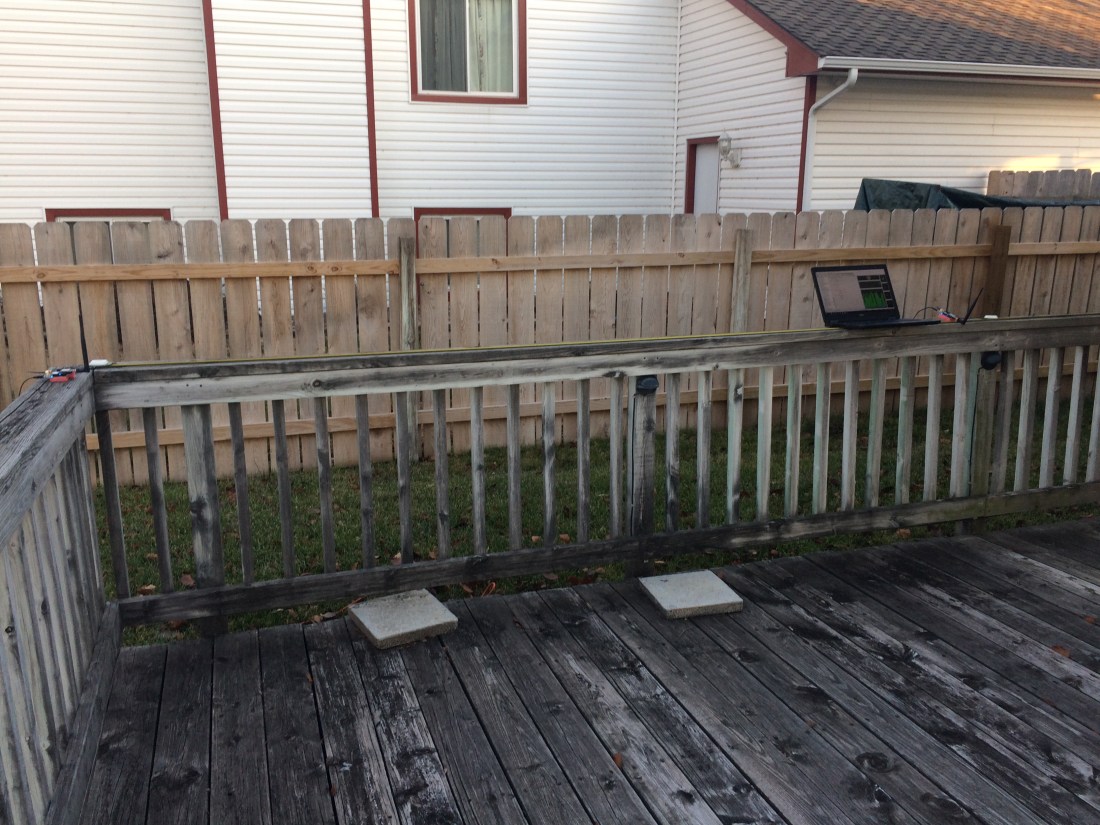
The test setup. The receiver on the left is the base, the on the right near the laptop is the rover. Yes, that is my neighbor’s two story houses in the background.
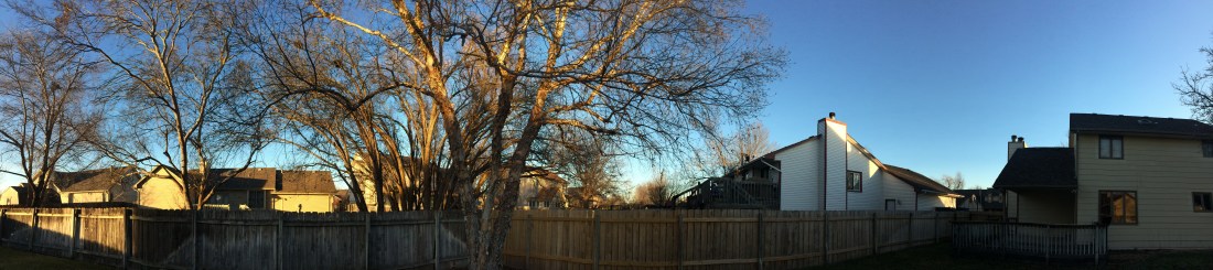
I intentionally placed the receivers in a really crappy area of my yard to see what these modules are capable of. My neighborhood has lots of two story houses, and many fully grown trees, although they are without leaves this time of year which certainly helps. Here’s a panoramic shot of the backyard, with my house to the right:
My backyard. The deck where the test was conducted is on the right.
Bottom line is that this was a pretty challenging multipath environment. I would estimate 50% of the horizon was occluded by my and my neighbor’s house. The remaining areas were pretty well covered up to about 20° if you exclude bare trees. How well did the modules perform?
It’s tough to see in the picture but the NED measures in meters are:
N = -2.1990 E = 0.1063 D = -0.0006
Using the 3D distance formula on these components and converting to inches gives a baseline distance of 86.6759in. You can see in the picture above that the rover antenna is sitting right at 87in. Holy geography Batman indeed!
Some Other Observations
A few other things I noticed in my brief time working with these modules:
The Ardusimple boards have the LED status “backward” from what you’d expect. No corrections means solid blue light, receiving corrections but no fix is blinking blue, and RTK fix is no light. Counter intuitive, but their documentation does mention this.
Just for fun I covered the antenna and waited for the light to turn on, indicating the RTK fix was lost. When I removed my hand, the light would turn back off consistently after less than a second. It appears that if you lose your fix with these modules, you can get it back very quickly, even in a challenging environment.
I kept moving the boards toward the alley between my house and my neighbor’s house, just to see what it would take to force the modules to lose the RTK fix and I was able to get as far as 227in from the base point in the picture above, which was about 3 feet away from my covered patio area before I lost my RTK fix.
Even after I lost the RTK fix, the baseline error was only 12in in 3D float mode. Still really good. Keep in mind during most of this test, I am standing at the laptop taking pictures and fiddling with u-Center. So my body is blocking some signals, too, I’d imagine.
So far these boards are looking awesome! Next step is to hook things up to the Pixhawk.
Here are my goals for the robot mower over the next few months. I need to plan and execute well so that the mower will be ready to cut grass this spring.
December
Finish designing the robot mower, including wiring and planned integration of the RTK GPS module. The module should arrive at the end of December. I promise I will post more about the RTK GPS module soon.
January
Send the robot mower weldments out for quote. I’ll also start sourcing purchased parts for the project. Any design changes based on vendor feedback will be incorporated during January. I’ll also start playing with the RTK GPS module, getting a feel for performance and how to configure the base station.
February
Select a vendor to build the weldment. Start receiving in purchased parts. Implement the RTK GPS module on the wheel chair robot and take it out for field testing. If the weldments are completed in February, we’ll start assembling the robot mower.
March
Finish construction of the robot lawn mower. Conduct functional testing. Make any last minute changes to the design based on the testing results. Continue field testing the RTK GPS module on the wheel chair robot.
April
Integrate the RTK GPS module on the robot mower. Start working on making the mower truly autonomous, with my backyard as the test bed. It’s fully fenced in so it should be a safe area, and the trees and houses nearby provide a fairly challenging GPS environment, perfect for working out the kinks.
The Bottom Line
Shoot for the moon; even if you miss, you’ll end up among the stars.
-Some motivational kindergarten classroom poster
I realize this is a very aggressive schedule, but it’s been my experience that if you aim high but miss, you still will still achieve a lot more than you would have if you had set a more “realistic” goal. So we’ll see how far we get over the next few months.
Get the rover tuned properly, and see if there is any strange autonomous behavior like weaving, jerking, etc.
Familiarize myself with planning autonomous missions in Mission Planner. I was specifically interested in seeing how to autogenerate waypoints.
See how well the GPS blending reports position. I was interested in both absolute and relative accuracy, but really just wanted to get a feel for things at this point.
To start, I took the rover V2 out in my backyard and got it to run autonomously, but my backyard isn’t very big. I have lots of tall trees in my neighborhood, too, so GPS signal reception wasn’t great either.
The rover V2 running to waypoints autonomously. I managed to avoid crashing into my sprinkler well the whole afternoon!
I would estimate position accuracy relative to the satellite map data was +/-3m. Not horrible, but not great, either. Throughout the afternoon position would drift slightly, I would estimate +/-1m.
I had the rover run an autonomous mission of 20 waypoints positioned in a circle several times to test repeatability. I did this close to 10 times over the course of an hour, and each time the rover took a slightly different path, as evidenced by the track marks in the grass. Sometimes the rover would go on the left side of my sprinkler well, other times to the right. Not very repeatable, but this was a somewhat challenging GPS environment.
So knowing that things were at least configured somewhat correctly I decided to take the rover V2 out to a large parking lot with a good view of the sky. In Kansas, those aren’t too hard to find. I chose a parking lot way out of town, with newly painted stripes that showed up on the satellite imagery so that I could have a good measure of relative accuracy.
The rover weighs something close to 100lb, so I had to take the batteries off of the chassis and remove both of the control boxes. I brought my tool box with me to help reassemble the rover and I also made sure my laptop was charged, but I forgot to bring a few things. If you’re ever out field testing, a checklist is a really good idea. Here’s mine for the next time I go out:
Cell phone with cellular data
AA batteries for the RC transmitter
Make sure rover batteries are sufficiently charged
The toolbox with hex wrenches, adjustable wrench, and screwdrivers
Multimeter
Laptop with a good battery charge
Telemetry radio for the laptop
SD card, installed in the Pixhawk
I asked my very supportive wife to go with me, thinking she would bring her phone and that I could use it as a wireless hotspot to download Mission Planner map data. I forgot to explicitly ask her to bring it, which was a huge mistake because this was the one time she decided to leave her phone at home. And I’m too cheap to have a data plan, so I was depending on her. We had a good laugh about it when we realized she’d left it at home.
So while I was able to do some autonomous missions, I was unable to compare the position data to the parking stripes on the satellite map. I could zoom in, but the ~300 car parking lot was reduced to 6 pixels in Mission Planner.
So without any good imagery, I took the rover manually around the parking lot perimeter to demarcate the edges and then planned some missions. The first ones were circular, and then I did some square ones, and some random ones.
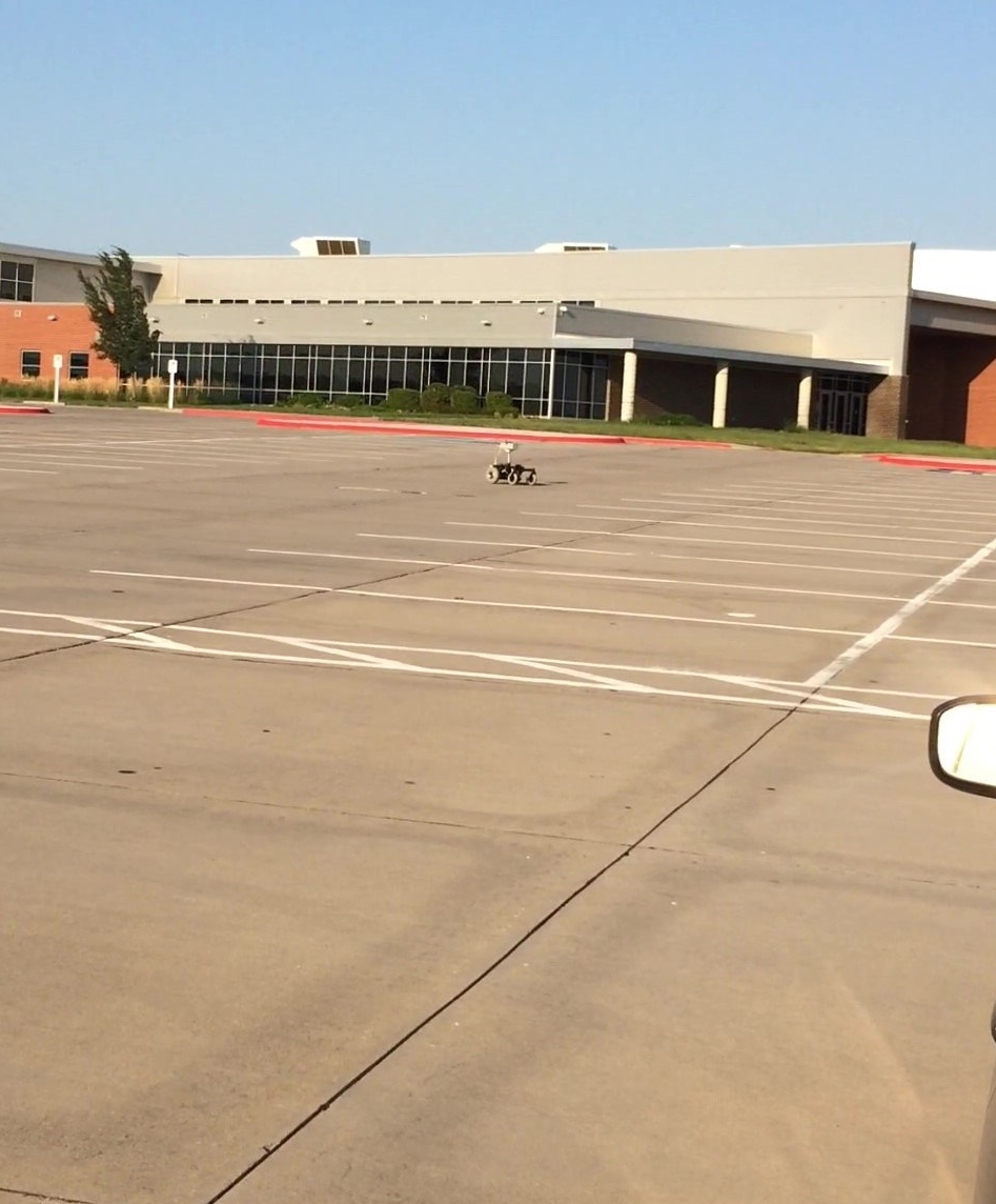
The rover V2 in the parking lot.
Overall, I felt like the rover was tuned perfectly. I had a few odd shimmies here and there, but I didn’t spend too much time trying to find the cause. They weren’t debilitating, just noticeable. Seeing the rover run autonomously without toilet bowling was very satisfying given my rover V1 experience.
So field testing was only a partial success. I felt like the rover was tuned really well with just the default settings, so that was a win. But I wasn’t able to get a good feel for GPS positioning accuracy or repeatability. I did get to spend some time familiarizing myself with Mission Planner.
An observation about field testing that may be specific to Kansas: Wind stinks. The laptop almost blew off the hood of my car while I was in the parking lot. I set up shop in the trunk of my car where I was sheltered from the wind a little, but I noticed this affected my radio range somewhat. I had the rover more than 500ft from my car at some points, and much past that things got spotty. In the future I’ll choose a calmer day for field testing.
Another observation: Kansas is flat. Very flat. When the rover got more than 200ft or so away from me distance to obstacles becomes very difficult to judge (especially with no satellite map). I hopped a few curbs in manual mode, but the rover V2 handled it like a champ.
Overall I’d say it was a 1.5 out of 3. We’ll bring a good cell phone and choose a calmer day next time.