The Productivity Problem: A Really Long Editorial

I like searching the internet for other people who are making autonomous lawn mowers. You can learn a lot by seeing how others are approaching the problem. Over the years, I’ve found several folks who’ve made great progress. Yet everywhere I look I still see people on riding mowers cutting their grass the same old-fashioned way. What gives?

When I started the mower project, the problem I was solving seemed blindingly obvious. Mowing is unpleasant to do personally and expensive to hire out. Let’s build a machine that mows a lawn without a human. It will sell itself!

Both Greenzie and Mowbotix did just that. They built machines that can mow huge fields with great precision. Why haven’t they conquered the lawn care industry with their cutting-edge technology? The answer, in my humble opinion, has nothing to do with the maturity or sophistication of their technology. It has everything to do with productivity.

If you think back to economics 101, you’ll recall that productivity is the amount of output you get for a given input. For an autonomous lawn mower to be successful in the marketplace, it has to not only remove the operator from the machine but increase productivity while doing so.

Joe’s Mowing Company.

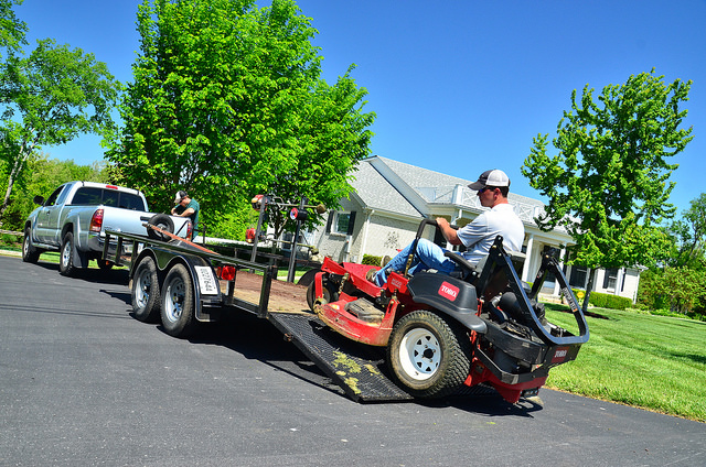
And therein lies the problem. To illustrate, imagine a fictitious Joe’s Lawn Care company, who is using standard lawn care technology available today. A typical day for Joe would go something like this:

  1. Joe drives to the job site he needs to mow.
  2. He unloads his mower, hops on, and starts cutting grass.
  3. When he’s finished, he loads the mower back on the trailer and drives to the next job site.
  4. He repeats steps 1 through 3 until he’s finished with the day’s work.

If Joe were to upgrade to an autonomous lawn mower, his day would look like this:

  1. Joe drives to the job site he needs to mow.
  2. He unloads his mower, opens his laptop, loads a mission, and starts cutting grass.
  3. When he’s finished, he loads the mower back on the trailer and drives to the next job site.
  4. He repeats steps 1 through 3 until he’s finished with the day’s work.

How much does an autonomous lawn mower improve Joe’s productivity? The answer: none. And that’s being generous.

Joe gets paid to be out there monitoring the autonomous lawn mower, even if he’s sitting in the truck sipping iced tea while it cuts the grass. He still needs to transport the mower to the job site, unload, and load it. In this light, an autonomous lawn mower doesn’t reduce Joe’s labor costs at all. In fact, it probably increases them because the setup time at each job site will be longer than the time it takes to hop on a riding mower.

And on top of that, an autonomous lawn mower will likely cost much more than a typical riding mower. To give you an idea of how much, I’ll direct you here and here. Essentially, Greenzie and Mowbotix are asking you to bring them your existing mower, $5,000, and they’ll retrofit it for autonomy.

The worst part? To use their solution, you need to pay a significant monthly fee. Wasn’t the whole point of this exercise to get rid of the monthly fee, i.e. the wages you pay the guy to run mower? Talk about back to square one. If that’s how we’re going to market the solution I understand why autonomous lawn mowers haven’t caught on yet.

Framing this information in productivity terms, the inputs for an autonomous mower solution:

  1. Cost thousands of dollars more than an ordinary riding mower.
  2. Still require a worker to setup, monitor, and load up when finished.
  3. Require a significant monthly fee to operate.

On the output side, you get to use your same riding mower at the same speed to cut the same amount of grass as before. And that assumes it doesn’t take longer to get the autonomous mower up and running once you’re at the job site.

I’m going to be honest, this has been a tough post to write because the solution I’m working on suffers from many of these same issues. I don’t intend to disparage Greenzie or Mowbotix: both of them have way cooler robots that are much more robustly autonomous than mine.

But as they exist today, these autonomous mowing solutions, mine included, cost more than traditional lawn mowing technology and result in about the same level of output. We’ve been solving the wrong problem, or a very small part of a much bigger problem.

Removing the operator from the machine is a step in the right direction, but to truly increase lawn care productivity it’s going to take more than a mower that can drive itself. I will be doing some pondering on that over the next few days.

I’ll leave you with a quote I wish I’d found back when Rod sold me the electric wheel chair many years ago:

It doesn’t matter how fast you move if it’s in a worthless direction. Picking the right thing to work on is the most important element of productivity and usually almost ignored. So think about it more!

Sam Altman

Please leave your thoughts below. I’d love to hear them!

A Better RTK Fix

Previously I was using GPS blending between a u-Blox NEO-M8N and a ZED-F9P. When the F9P had an RTK fix solution, all was well. But after losing the RTK fix, the position estimate reverted to the inferior M8N position solution.

So I conducted a few experiments to see if there was a way to get a better position estimate. I realized while tweaking parameters that the final position estimate is what we’re really trying to improve, not just the quality of our RTK fix from the F9P module. A better RTK fix will help our position estimate, but that’s only part of the equation.

Instead of feeding arbitrary coordinates into the base F9P module, this time I let it survey in with a precision of 2.5m and a time of 300s. I was surprised how close to the map imagery the survey in solution was. It was off by ~18in would be my guess.

I started by unplugging the M8N module, but unfortunately the compass is also powered by the 5V and GND pins on the data cable. So with both modules active, I set the GPS_AUTO_SWITCH parameter to 3, so that only the second GPS, the F9P, would be used.

This was a great way to test things because the flight controller was still logging the M8N data, but it wasn’t used for computing the robot’s position.

I was skeptical that this change would actually improve things because the F9P maintains an RTK fix only intermittently at best. But the results surprised me.

without rtk fix good pos
An excellent position estimate even with spotty RTK fixes.

The Ardupilot software has some magic in it (meaning code I don’t currently understand) that allows the rover to continue with high accuracy even without a GPS solution at times. I think the wheel encoders are helping significantly in this regard but I can’t say for certain.

And related, the blue line is the M8N position accuracy. It’s really terrible. At times it’s a parking stall width, about 2m, from the RTK fix position. In hindsight, I was corrupting a really good position solution by blending it with a solution that was always off by at least 2m.

I looped the same square mission about 20 times and placed screwdrivers on the asphalt at the center of the robot’s travel to mark it’s path and check its repeatability. I would estimate the path drifted ~4in over the 20 loops.

Here’s a picture of the first few loops of the mission. Even with some hiccups in the RTK fix solution, the overall position estimate is very good.

multiple loops
Several loops of the square mission. Even with some bad position data from the ZED-F9P module (green track) the position estimate (red track) is still rock solid.

I didn’t realize it until I started reviewing the logs, but the cell phone battery pack that I was using to power the base F9P module went to sleep after about 10 loops. That means no RTCM stream from the base, which means no RTK fix at the rover. But even without an RTK fix for 10 loops, the position solution was still very good.

no rtk
The position solution with only a 3D Fix from the ZED-F9P. The red track is still solid.

In hindsight, the repeatability could be even better than ~4in that I was seeing if we could have intermittently re-established an RTK fix during that time.

Moral of the story: don’t ruin a really good answer (RTK fix) by averaging it with a really bad answer (3D fix).

A Day in the Parking Lot

IMG_1532
Transporting the robot lawn mower. With the lead acid batteries installed, it weighs close to 300lb.

Late last year I traded in the Honda for a small truck. As I was designing the robot lawn mower it quickly became apparent that it wouldn’t fit in my little sedan. And even if it could, I’m not sure how I would load and unload a machine that weighs 300lb by myself.

I thought about taking it apart to transport it and then putting it back together in the field. But that is a very inefficient way to do business. The Honda had a great run, it was 16 years old and needed a new timing belt so I figured it was time to upgrade.

I’m a big fan of goals. For my afternoon in the parking lot, here was my to do list:

  1. Figure out the best way to load and unload the robot mower into the truck.
  2. Install my new wheel encoders and make sure they are working robustly.
  3. Play with the RTK GPS modules.
  4. Take the robot into some tall grass and see how it performs.

I realized that I have a few more things I need to bring to the field with the new robot lawn mower, so I updated my checklist of things to bring or do prior to leaving the house:

  1. Cell phone with cellular data and enough storage space for several videos and photos
  2. AA batteries for the RC transmitter
  3. Make sure rover batteries are sufficiently charged
  4. The toolbox with hex wrenches, adjustable wrench, and screwdrivers
  5. Multimeter
  6. Laptop with a good battery charge
  7. Telemetry radio for the laptop
  8. SD card, installed in the Pixhawk
  9. RTK GPS receiver, antenna, and micro USB cable for power
  10. Rechargeable batteries for RTK GPS base station
  11. Prefetch any map data that will be needed in Mission Planner
  12. Preplan any missions that may be needed and save the waypoint files

I typically would have gone to an actual field, but a parking lot offers some really nice geostationary markers that show up on satellite imagery: parking stripes.

IMG_1534
The parking lot. Wide open skies, flat pavement, and geostationary lines. A perfect laboratory for implementing the RTK GPS modules.

My neighbor saw me using chunks of plywood to load the robot in the truck. He had some tailgate ramps he wasn’t using and let me borrow them for the day. I think I’m going to make him an offer for them. They were tremendously easy to use and transport.

The roof of a car makes for an awesome ground plane, so I decided to set up the RTK GPS base station on top of the truck. I noted which parking stall I was in and then found that same stall on the map imagery in Mission Planner and fed those coordinates to the ZED-F9P module.

To get a feel for how the RTK GPS was performing, I ran a circle mission.

perfect circle mission
A circle mission in the parking lot with RTK GPS.

On the map, the green line is GPS2, the position solution from the ZED-F9P module on the rover. The blue line is GPS1, the NEO-M8N module. My understanding is the red line is the EKF’s estimation of position after fusing sensor data with the GPS data.

The blue line is offset from the green line, even though their paths are pretty similar. I think this is because I arbitrarily selected the location of the base module. Essentially, I’m using two different origins: one for the RTK GPS versus whatever the M8N uses. This poses a problem when you lose the RTK fix.

bad gps
An example of how the position solution from the EKF jumps when RTK fix is lost.

The ZED-F9P module doesn’t lose the RTK fix gracefully. It frequently goes from RTK fix to no solution. After a few seconds though it usually returns to an RTK fix. But once it’s lost, the EKF replaces the F9P position solution with the M8N’s solution. Which is off by a few feet.

You can see an example of this behavior in the picture above. The position is heavily weighted to the F9P solution, but once it’s lost, it jumps immediately to the M8N solution. Interestingly, when the F9P reports an intermediate solution such as 3D fix, the weighting behavior is more of an average between the two receivers.

I double checked my parameters and GPS_AUTO_SWITCH = 2, so the EKF should be blending solutions, not just using the most accurate solution of the two. And when both receivers are in 3D fix mode, that’s the behavior you see.

I have some questions based on these observations:

  1. Is GPS blending really that useful? Maybe I should just ditch the M8N module all together. Whenever you have an RTK fix, it seems like this solution is so superior that the EKF basically ignores the M8N solution.
  2. For GPS blending, would an additional RTK GPS help? The reported accuracies from two identical modules would be similar. Maybe the redundancy would help when an RTK fix is lost on one receiver.
  3. Why does the EFK assume the robot’s position suddenly jumps? This is a rover, not a quadcopter. Especially when you have wheel encoders and an IMU, you should be able to assume that the robot’s position isn’t drifting significantly due to external disturbances, even if the GPS position jumps.
  4. If we could eliminate the offset between the two solutions by using the same “datums” would that make the failover more graceful?

Some of those questions can be turned into experiments I can conduct the next time I’m out in the field:

  1. Disable the NEO-M8N module. How does the robot respond when the ZED-F9P module loses an RTK fix?
  2. Instead of arbitrarily setting the coordinates of the RTK base module, we can let it “survey in” to determine its location. This may eliminate some of the offset between the F9P and M8N position solutions.
  3. We can measure the offset between the F9P and M8N solutions and then adjust the coordinates of the RTK base module to compensate. This would minimize the position jump between solutions when RTK fix is lost.

I also took the robot out into some taller grass to see how it would perform. You can see a video of it here. I also took a time-lapse of a typical grid run. Overall not bad, but for striping grass, it’s not good enough.

Going forward it looks like I will need ways to obtain a better position solution. I don’t think RTK GPS will get us there entirely. There are some exciting visual odometry solutions out there I may look into.

Rotary Encoder Troubleshooting

I’ve managed to fry three rotary encoders on the left motor now. The first one was when I discovered the issue. The second one was when I switched the left and right encoders to try and see if the issue was specific the encoder or something else. And the third one was a spare 900CPR encoder I plugged in just to see if it would work.

When I write computer code, I’m pretty cavalier about testing it. If I get an error, I just go back to the code and tweak it. The computer typically doesn’t go up in smoke if I forget a parenthesis or colon.

On the robot lawn mower, however, there are consequences for this kind risk taking. Installing a new encoder in a scenario where I’ve just watched one get fried is, well, pretty stupid. The results are predictable.

Because they’re not particularly cheap, I decided it would be best to sit down and figure out exactly why the encoders keep breaking. To summarize the symptoms:

  1. Only the encoder on the left motor breaks. The encoder on the right motor works fine.
  2. After installing a new encoder on the left motor, it will work fine for a while, but eventually stops working.
  3. When an encoder fails, it will oscillate around the zero point by a few counts. It still outputs data, it’s just really crappy data.

After installing the encoders and building the drive motor assemblies, I bench tested the encoders. I wanted to make sure I caught any issues before I installed them on the mower. They worked great at the time, but I only applied 12V to the motors. They receive 24V the way they’re wired in the robot lawn mower.

So my initial hypothesis was that perhaps the current sent through the motor wires was inducing current in the adjacent encoder wires. Maybe at 12V it’s not enough to matter, but with 24V, it causes an issue. The maximum current rating for the E5 encoders I’m using is 85mA, not much. But if this were the case, you would think the same issue would present itself on the right motor. They’re wired identically, but the right motor works just fine. So that can’t be the problem.

After tracing my wire runs and verifying everything worked, I was at a loss as to what was causing the issue. So I took apart the motor to see if something weird was going on inside.

IMG_5569
Encoder signal sires inside the cap of the motor housing. No wonder I kept frying encoders. The purple wire was to the A input of the encoder.

Well, a nicked signal wire could definitely cause an issue.

The two brass extrusions on the left and right side of the picture are for seating the motor brushes. With all the exposed, energized metal in this area it wouldn’t surprise me if the wire made contact with something and fried the encoder.

I’m guessing I pinched the wire when I installed the cap. It’s pretty tight in there and you kind of have to hammer it into place. You’d have no idea something got pinched until, well, the encoders stopped working.

After replacing the encoder wires and rebuilding the motor, I used the 900CPR encoder to make sure things were working. So far so good. Hopefully I’m done buying rotary encoders for a while.

ZED-F9P Notes

I updated the firmware for my SimpleRTK boards this evening. Below are my notes for the process in case I need to do it again. There was some obscure information I had to hunt down to get things working right, and I’m linking to it here so it will be available in the future after I’ve forgotten.

  1. Download the latest firmware from the u-Blox website. As of this writing, HPG112 appears to be the latest and greatest. Save it to your computer to a place you can get to it.
  2. Open up u-Center, u-Blox’s GNSS evaluation software.
  3. Connect the GNSS module you want to update to your computer via USB cable. Connect to the appropriate COM port within the u-Center software by going to Receiver > Connect.
  4. Within u-Center, go to Tools > Firmware Update. Navigate to the location of the firmware .bin file and check the boxes as shown below.

    firmware update
    The settings I used at the advice of the ArduSimple website.
  5. In the lower left of the Firmware Update Utility window, there should be a green Go button. Click it to update the module.
  6. Repeat this process for the second ZED-F9P module.
  7. I reset the configuration files for both modules to the default provided by ArduSimple. You can find those configuration files on their GitHub page. Download both and save them to a location you can get to. I have the LR xBee radios, so I used their srtk2b_rover_FW_HPG112.txt and srtk2b_base_FW_HPG112.txt files.
  8. To upload a configuration file, go to Tools > Receiver Configuration.
  9. Before you upload the configuration files, it’s not a bad idea to back up the existing ones. Use the Transfer GNSS > File button to create a backup.
  10. To upload a new configuration file, select the appropriate configuration file for either the base or rover module you’re connected to and use the Transfer File > GNSS button.

    loadsave receiver config
    The Receiver Configuration window. Save a back up of your existing configuration, just in case!
  11. I got a warning that said the firmware version of the module didn’t match the configuration file. I took a gamble and ignored this message. Things turned out okay, as of this writing.
  12. Repeat this process for the second module.
  13. Unfortunately, after updating the firmware and the configuration files, the xBee radios weren’t working. I found this thread on the ArduSimple website to be helpful. Basically, after you upload a configuration file, you have to save the configuration. It doesn’t do so automatically.
  14. To save the configuration, you need to go View > Configuration View, and then click on the CFG option in the left panel on the screen.
  15. There should be a radio button labeled Save Curent Configuration. If it’s not selected, select it. Then click Send in the lower left of the window. This will send a save command to the module.
  16. Take the modules outside and test them. I connected both to my laptop so I can toggle between the two in u-Center to make sure the base module reports TIME and the rover module reports 3D/GNSS/FIXED in the black window that has the latitude, longitude, and altitude shown.
  17. If you don’t see TIME on the base, you’re not sending RTCM correction messages to the rover. On the ArduSimple modules, the GPS > XBEE or XBEE > GPS LEDs should blink on both modules if the base reports TIME.
  18. To make sure corrections are being broadcast form the base and received by the rover, I went to View > Messages View and then click UBX > NAV > RELPOSNED. There should be a length in that window that should roughly match the distance between the antennas.

I also discovered that in order to set the survey in or fixed location of the base, you need to go to View > Generation 9 Configuration View and then select the Advanced Configuration option on the left of the screen. Under the CFG-TMODE option you can set the base behavior.

If you want to set fixed coordinates for the base you need to change CFG-TMODE-MODE to E1 – 2 – FIXED and then plug in either the north, east, down (NED) or latitude, longitude, and height (LLH) values for the base location. u-Center requires you do provide it with LLH in 1e-7 degrees, so 12.3456789° is 123456789 in the value field.

Mower Deck Installation

IMG_5459
The prototype lawn mower with the mower deck installed.

I got the mower deck installed this afternoon. I finally have a robot mower! I chose not to install the mower blades for the time being. I figure now is a really bad time to end up in a hospital, and I can still test the motor functionality without them.

I was worried that there wouldn’t be much clearance between the deck and the front swivel casters and that the front motor would interfere with the battery bay. The clearances in these areas were pretty tight in the CAD model and I was expecting some variance in the parts. Everything fit together pretty well though.

One thing didn’t though:

IMG_5450
The bushing that came with the cable gland I used to route the deck motor cables. Not even close to the right size.

I incorrectly sized the cable glands for the mower deck motor cables. I could barley cram both cables through the gland without the bushing. But after some finagling I was able to get it squeezed through there.

I picked the smaller size on purpose thinking it would be tough to get the bushing to seal around two cables. The two wires are 0.18in diameter with the insulation, which means I should have used a 0.375in ID bushing.

But plugging that size cable gland into the CAD model looked pretty ridiculous with lots of empty space in the bushing on both sides of the two cables. So I undersized it, and here we are. Lesson learned: your CAD model can be deceptive when dealing with flexible materials.

IMG_5452
One of the turnbuckles used to attach the rear of the mower deck to the robot.

The turnbuckles worked pretty slick for leveling the mower deck. You could pretty easily get your fingers in there to rotate them and adjust things. Getting the deck mounted though was a two person job. I had to ask Mrs. Mower for help. Once you have one of the rear turnbuckles attached the rest is pretty easy.

Unfortunately, the deck does still sway a little when driving the robot around. Nothing terrible, but not perfect either. I think I will try to make a custom turnbuckle for the front deck attach point. There’s a lot of motion at the joint between the turnbuckle and the linkage.

Now for the hard part: making it autonomous.

The Prototype Robot Lawn Mower

IMG_5418
The prototype robot lawn mower, without the mower deck.

I was able to take the prototype robot lawn mower out for a drive this week. Watching the design drive off the computer screen and into my backyard has been immensely satisfying. Below are my notes from a day spent becoming better acquainted with the robot mower.

Vehicle Handling

Initially I wired the RC receiver straight into the Sabertooth so I could take it out for a drive. I’d forgotten how much smoothing the Ardupilot software adds to the control output. The robot was almost too responsive without it.

But overall, it handled wonderfully. I was almost able to drive up the curb from my street into my yard, but there wasn’t enough traction to get the back wheels up the curb. So far, so good!

However…

IMG_5416
A scenario I hadn’t considered when I designed the robot mower.

After I got the Pixhawk wired up (more on that below) I ran a few autonomous missions and started tuning the steering and throttle PID values. At lower steering turn rates, I noticed the swivel caster wheels sometimes catch on the grass instead of swiveling, and the whole setup actually rotates about the center pin. The scenario in the picture above only occurred once, but I noticed the wheels getting hung up more than once.

When I was putting the robot together, I noticed the casters weren’t fabricated per my print. I had designed them with more offset between the wheel axle and the swivel axis. If this continues to be a problem, I’ll have them remade with a little extra offset so they swivel easier.

Wires

Getting the robot wired correctly was nerve wracking. I made a wiring diagram for the power enclosure and modeled up all the components and connections to make sure they fit, but I skipped this planning step for the Pixhawk enclosure. The amount of wires I had to route to the Pixhawk multiplied quickly:

  1. 5 wires from the drive wheel rotary encoders, a total of 10 for both motors.
  2. 4 Sabertooth control wires.
  3. 4 relay control wires.
  4. 6 wires for the Pixhawk power port.
  5. 2 emergency stop wires.
  6. 2 additional wires to power the servo rail on the Pixhawk.

I wasn’t expecting 23 wires needing to be routed to the Pixhawk enclosure, and making sure I didn’t get something wired incorrectly was nerve wracking.

And ultimately, I did wire something incorrectly. When I first powered the robot on, nothing happened, other than the Mauch BEC getting hot. And that’s never a good sign.

Turns out I had incorrectly wired the servo rail by swapping the + and – wires. Yikes. I eventually discovered the issue and fixed it, but not before learning a lot about the LM2576 voltage regulator I incorrectly thought was the issue.

Wheel Encoders

After I fixed the wiring, everything seemed to work, until I started running autonomous missions and had trouble getting the MAVLink Inspector within Mission Planner to show wheel encoder data. Initially I couldn’t even find the wheel encoder message. But after a few reboots it magically appeared. Not sure why it wasn’t visible from the start.

From the get-go, only the right wheel encoder was working. Below is WENC.Dist0 for the encoder on the left motor and WENC.Dist1 for the encoder on the right motor.

kind of bad encoder
Wheel encoder total distance traveled as measured from the right and left wheel encoders. Note that WENC.Dist1 is 0.

And below is what the graph for the right encoder by itself, WENC.Dist1 versus time, looks like.

bad left encoder
The right encoder odometry data. Having watched the robot move around my backyard, I know this can’t be correct.

So to troubleshoot, I swapped the encoders. The idea is that WENC.Dist0 should look like the graph above and WENC.Dist1 should look like more like the first graph, with values much greater than 10E-6 and gradually increasing. This would isolate the issue to the encoder and not a settings, wiring, or Pixhawk error.

As an aside, having posted that graph I’m now wondering if the negative value means I have the A and B wires swapped. I was driving the robot forward mostly, so I would expect the values to be increasing, not decreasing. Regardless, at least the left encoder is obviously outputting some kind of useful data.

After swapping the encoders…

bad encoder
The WENC.Dist0 and WENC.Dist1 values after swapping the encoders.

Great, now they’re both broken!

I decided to call it quits after this because the sun was going down. I took the robot back into the garage and got the Arduino out to see what it said about the encoder output. Unfortunately it confirmed that the left encoder at a minimum was broken. The Arduino sketch counted pulses and only got up to 1 or 2 regardless of how much the wheel was rotating.

I remembered I had some 900CPR encoders I had purchased a while back and decided to see if I could get them to work with the Pixhawk. So I swapped the 32 CPR encoder with the 900 CPR encoder, and lo and behold, it started to work again.

All I can gather is that I must have fried one or both of the encoders with my wiring shenanigans. But it concerns me that one of the encoders was working at the start of the day and stopped working by the end of the day.

More to come once I get the mower deck assembled and installed. You can find a brief video of the rover doing an autonomous mission in my backyard here.

Assembly

IMG_5301
The chassis of the robot mower with wheels and motors installed.

I finally have all the parts I need to start putting the robot mower together. And for better or worse, my company has furloughed us for the next four weeks. Here’s hoping I get to cut some grass over the next few weeks!

Finishing Touches

Drawing pictures in a CAD program is fun, but when the rubber meets the road and you start fabricating something, you quickly notice some areas that weren’t too well thought out. Lately I’ve been backfilling those issues as we discover them at the shop. Here are some things I’ve tweaked over the past few weeks. Hopefully we’ll have a finished robot lawn mower soon!

Mower Deck to Chassis Interface

When the deck is stationary in my CAD program, chains look like a great way to support it. I can flip the model upside down and they don’t even move! But when the robot lawn mower starts rolling in reality, what keeps the deck from swaying all over the place? Well, if it hangs from chains, the answer is nothing.

IMG_5142
The turnbuckle that will replace the chain used to attach the mower deck to the chassis.

Unfortunately, the chassis weldment and the mower deck weldments are pretty much complete. So whatever fix we come up with has to interface with those features like the chain did. The solution? Turnbuckles! Some really small turnbuckles, to be exact.

The eye on these little guys is 0.26in ID, perfect for the 1/4-20 screw I had planned on using. The length is adjustable from 3.375in to 4.625in long. They’re rated for 36lb, a strangely specific number, but with three of them they should work fine. The mower deck weighs just over 30lb.

Steel Mower Blades

Another issue the shop made me aware of was the mower blades. I don’t remember if I mentioned it or not, but the reason I designed the robot lawn mower out of aluminum was to avoid any compass interference issues. You may recall I ditched the compass a few months ago, but I never went back and changed the design to steel.

The shop thought that aluminum mower blades were a goofy idea. They’re not wrong, but at least I had a reason for making them that way. Kenny Trussell discovered that when the blades spool up to speed, they interact with the earth’s magnetic field in a way that skews your apparent compass heading.

Making them out of aluminum would avoid that issue, as they’d be non-ferrous. But since we’re not using the compass anymore, it seemed like a reasonable change to make. Besides, all the mower blades you see out in the wild are made from steel.

And if there’s one thing I’ve learned working with fabrication guys, if they make a suggestion that doesn’t impact your design significantly and doesn’t cost much, change it. It’s an easy way to show them you value their input, and they’ll do whatever it takes to get your design working now that their finger prints are on not just the physical parts, but the design, too.

A Legit GNSS Antenna Enclosure

On the wheelchair robot, I had the two GNSS modules velcroed to the top of the robot. That doesn’t seem befitting of a robot I’ve spent a year and a few thousand dollars making. So I designed a small 3D printed enclosure for the RTK GNSS antenna and the UBlox M8N module. It sits on top of a small ground plane disk, mounting to the lid of the electronics enclosure.

gnss enclosure
A 3D printed GNSS antenna enclosure. The larger GNSS antenna is for the Ardusimple RTK GNSS module. The smaller one is a UBlox M8N.

Everybody I talk to says you need a really good ground plane for your antennas. That’s what the circular disk is below the enclosure. The screws for the lid of the enclosure are plastic. Hopefully this doesn’t create any reception issues. I also hope that the antennas don’t have to be perfectly concentric with the ground plane. If anybody has experience with ground planes, I’ll take any advice or feedback you can give me!

Mower Deck Discharge Chute

For some reason I had it on the left side of the mower deck. The shop mentioned that most mowers have the discharge chute on the right side of the deck. I don’t want people latching on to minor quirks of my design, so changing it to the right side seemed like a good idea.

Mower Deck Progress

Here’s the progress on the mower deck last time I visited the shop. We’re a few roll formed parts short of a robot lawn mower!

mower deck
The mower deck weldment just before Christmas, 2019.

The Time Flies

Back when I was ordering hardware for the robot lawn mower, I came across a smoking deal on some 5/8-11 X 5.5in long socket head cap screws. I was browsing Grainger’s website and they had a deal for a box of five for $1.92. Hot dog! Those things are $4+ a pop at most other places. I placed an order without thinking twice.

I opened the box up today when I was putting the front caster assembly together and found this newspaper page stuffed inside the box. Talk about a blast from the past. I assume this means these screws sat in that box for almost 12 years before they sold. No wonder they were on sale!

IMG_5088
A newspaper page I found inside my box of five 5/8-11 X 5.5in long socket head cap screws. The reverse of this page was a full page ad for liquor store in New Jersey.

Looking at the picture of those girl scouts got me thinking about how short life is. There’s a good chance those girls are probably out of college by now. I wonder if any of them even remember the Girl Scout Sunday events on March 11, 2007. It was probably a big deal at the time, but 12 years later, I’m sure it’s but a distant memory to most of them.

Seeing this newspaper page was a good reminder to cherish what’s really important in life: family and friends. The Mower Project is a lot of fun, but without good friends and family to share my successes, failures, dreams, and goals, it’s all a very empty exercise.

And beyond that, it’s sobering to look forward and think about what will really matter 12 years from now. Who knows where the mower project will take me? The work I put in here could be a defunct blog 12 years from now. It could be something else, I’m not sure what. But if it comes at the expense of time spent with family and friends, it will surely not have been worth the effort.

This Christmas, I hope you all have a wonderful time with those closest to you, and I hope you make some beautiful memories with your loved ones, on which you’ll look back on 12 years from now and smile. That’s a project worth every minute.

Merry Christmas!