This weekend I had some time to install my emergency stop switch. At first I thought I would keep things simple and just mount the emergency stop switch on top of the control enclosure and route one of the battery wires straight through the safety switch. Sounds simple, right? This method, however, presents two big issues:
Hitting the emergency stop switch shuts power off to the entire rover.
A high current carrying wire has to run through the control enclosure.
The first item above is an issue because we want to be able to communicate an emergency shut down state to the ground control laptop. If all the power is shut off to the rover, a power failure and an emergency shut down will appear identical from the ground control’s perspective.
The second item is an issue because it defeats the purpose of separating the power and control electronics. The constraint here is that the emergency stop switch has to be mounted on top of the control enclosure so it is visible, accessible, and in a safe location, but we can’t have a high power wire running through it. We want to keep those noisy high current wires away from sensitive electronics.
The solution? A relay! Or more specifically, a set of relays. We’ll have the emergency switch trigger a relay that cuts power to the drive motors only in an emergency state. We’ll also keep all the high current wires contained to the power enclosure.
The wiring diagram for the emergency stop system.
The FIT0156 emergency stop switch has two integral switches triggered by the big red button. One is NC and the other is NO. Our system uses the NC switch. When the button is pressed, the switch opens and prevents 5V from flowing to the CH1 and CH2 pins on the relay module. This opens the motor circuit, immobilizing the rover.
The IM120525001 2 channel relay was only $3, but I wasn’t sure if it would be large enough to conduct the current needed by the motors. I decided to take a gamble, and I’m glad I did. The module works very well. The spec sheets say it can conduct up to 30A at 24VDC. The only drawback is that the screw terminals on the module aren’t big enough for 14 gage wire. I had to use 16 gage wire instead.
I measured current flow between the 5V output on the Mauch BEC and VCC on the IM120525001 module and my ammeter said it consumes 170mA, a little bit high for my liking, but manageable. The Mauch BEC is rated for 3A, so it shouldn’t be a big issue.
I oversized both enclosures knowing there would be additional things I add later, and I am glad that I did. The emergency stop switch and relay module both fit nicely in my enclosures.
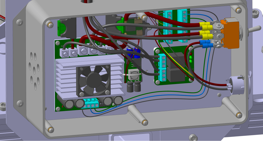
The power enclosure with the relay module mounted nicely in the lower right. Both of the motors have one wire routed through the relay module before connecting to the Sabertooth motor controller.
I used one of my remaining 8 pins on the DB15 breakout board to route the emergency stop switch down to the power box. This wire goes to both the CH1 and Ch2 pins on the relay module. When you hit the button both motor circuits are opened.
The big red button installed on the rover. Be sure to include large, clear signage stating that this is how you shut it off!
So the total cost of our emergency system:
Emergency stop switch, $6
Relay module, $3
Emergency stop sticker, $2
Miscellaneous wire, $1
Tack on a few dollars for shipping and sales tax for those items and you’re still easily under $20. Not too shabby.
Eventually the rover will have a spinning blade of death on it. Before we get to that point we need to include some safety mechanisms. Let’s be real: these features aren’t just for innocent bystanders. You’re the one tinkering with this thing. Do yourself a favor and invest in some simple safety features. They don’t have to be expensive or complicated.
Safety is your responsibility! Only you can keep this adorable kitty cat safe.
The goal of a safety system is to ensure that at all times the rover is in a safe state. What is a safe state, you ask? Well, that depends. Say the spinning blade of death is barreling toward a small kitten. A safe state would be one in which it stops barreling toward that kitten. So tell the motors to stop spinning, right?
Well, maybe. But what if the rover is on an incline, and could start rolling backward? That’s certainly not safe. Well, then put the brakes on, you may say. Sure, that might work. But what if you already hit the kitten and the poor thing is stuck under the spinning blade of death already? Now what?
The above scenario may seem preposterous, and it is unlikely. But it illustrates an important point: you need to be proactive about identifying safetyrisks.
Safety system design is a whole discipline in itself, but there’s one thing we can all agree on: a safe state is one in which the spinning blade of death stops spinning. So let’s add a simple emergency stop switch to shut off the spinning blade of death.
Right now our rover isn’t equipped with such a feature, but we can wire it into the drive motors so that when you hit the emergency stop switch, the rover stops moving. Down the road we’ll also wire it into the motor powering the mower blade.
The big red button. Nothing screams Emergency Stop like that danger red.
So what goes into an E-Stop?
I don’t need an emergency stop switch. I have an on off switch and I’m smart enough to know how to use it.
-Me, before the rover slams into my shin
For an emergency stop switch to do any good, it needs to be identifiable. Think you’re on off switch is good enough? It may be for you, but can a person who has never seen your rover before identify it? Possibly, but we can’t assume that. Our emergency stop switch needs to be a big red button with a giant label by it saying Emergency Shut Off Switch or something of that nature. This way your grandma could easily figure out that this button will turn off the spinning blade of death.
Your E-stop also needs to be accessible. This means that it can be easily pressed by anyone. It’s not on the back side of your rover near the bottom. It’s front and center, located in an area where a person could quickly press the button if your rover were coming right at them. Set it at a height that your 4 year old niece could reach if your rover is of any significant size. What good is an E-stop if it can’t be reached?
Related to making your E-stop accessible, be sure to put it in a safe location. I know, that sounds awfully obvious, but be cognizant of what’s around your button. Is there a hot surface near it? Bad place for your E-stop. Is it near your spinning wheels? Also a bad place. Use common sense.
Lastly, your E-stop should put the rover into a safe state. What that looks like depends uniquely on your situation. In this case, it means the motors are de-energized.
Next time I’ll show what this kind of system looks like for the rover V2.
Get the rover tuned properly, and see if there is any strange autonomous behavior like weaving, jerking, etc.
Familiarize myself with planning autonomous missions in Mission Planner. I was specifically interested in seeing how to autogenerate waypoints.
See how well the GPS blending reports position. I was interested in both absolute and relative accuracy, but really just wanted to get a feel for things at this point.
To start, I took the rover V2 out in my backyard and got it to run autonomously, but my backyard isn’t very big. I have lots of tall trees in my neighborhood, too, so GPS signal reception wasn’t great either.
The rover V2 running to waypoints autonomously. I managed to avoid crashing into my sprinkler well the whole afternoon!
I would estimate position accuracy relative to the satellite map data was +/-3m. Not horrible, but not great, either. Throughout the afternoon position would drift slightly, I would estimate +/-1m.
I had the rover run an autonomous mission of 20 waypoints positioned in a circle several times to test repeatability. I did this close to 10 times over the course of an hour, and each time the rover took a slightly different path, as evidenced by the track marks in the grass. Sometimes the rover would go on the left side of my sprinkler well, other times to the right. Not very repeatable, but this was a somewhat challenging GPS environment.
So knowing that things were at least configured somewhat correctly I decided to take the rover V2 out to a large parking lot with a good view of the sky. In Kansas, those aren’t too hard to find. I chose a parking lot way out of town, with newly painted stripes that showed up on the satellite imagery so that I could have a good measure of relative accuracy.
The rover weighs something close to 100lb, so I had to take the batteries off of the chassis and remove both of the control boxes. I brought my tool box with me to help reassemble the rover and I also made sure my laptop was charged, but I forgot to bring a few things. If you’re ever out field testing, a checklist is a really good idea. Here’s mine for the next time I go out:
Cell phone with cellular data
AA batteries for the RC transmitter
Make sure rover batteries are sufficiently charged
The toolbox with hex wrenches, adjustable wrench, and screwdrivers
Multimeter
Laptop with a good battery charge
Telemetry radio for the laptop
SD card, installed in the Pixhawk
I asked my very supportive wife to go with me, thinking she would bring her phone and that I could use it as a wireless hotspot to download Mission Planner map data. I forgot to explicitly ask her to bring it, which was a huge mistake because this was the one time she decided to leave her phone at home. And I’m too cheap to have a data plan, so I was depending on her. We had a good laugh about it when we realized she’d left it at home.
So while I was able to do some autonomous missions, I was unable to compare the position data to the parking stripes on the satellite map. I could zoom in, but the ~300 car parking lot was reduced to 6 pixels in Mission Planner.
So without any good imagery, I took the rover manually around the parking lot perimeter to demarcate the edges and then planned some missions. The first ones were circular, and then I did some square ones, and some random ones.
The rover V2 in the parking lot.
Overall, I felt like the rover was tuned perfectly. I had a few odd shimmies here and there, but I didn’t spend too much time trying to find the cause. They weren’t debilitating, just noticeable. Seeing the rover run autonomously without toilet bowling was very satisfying given my rover V1 experience.
So field testing was only a partial success. I felt like the rover was tuned really well with just the default settings, so that was a win. But I wasn’t able to get a good feel for GPS positioning accuracy or repeatability. I did get to spend some time familiarizing myself with Mission Planner.
An observation about field testing that may be specific to Kansas: Wind stinks. The laptop almost blew off the hood of my car while I was in the parking lot. I set up shop in the trunk of my car where I was sheltered from the wind a little, but I noticed this affected my radio range somewhat. I had the rover more than 500ft from my car at some points, and much past that things got spotty. In the future I’ll choose a calmer day for field testing.
Another observation: Kansas is flat. Very flat. When the rover got more than 200ft or so away from me distance to obstacles becomes very difficult to judge (especially with no satellite map). I hopped a few curbs in manual mode, but the rover V2 handled it like a champ.
Overall I’d say it was a 1.5 out of 3. We’ll bring a good cell phone and choose a calmer day next time.
One of the painful experiences I had on rover V1 was getting the motors to turn the correct way. It sounds simple enough, but there are several different variables that control motor rotation direction and behavior:
Motor wiring polarity. How you connect the two wire leads on the motor into the Sabertooth motor controller affects rotation direction.
DIP switches on the Sabertooth motor controller. There are 6 on-off switches on the Sabertooth that determines how it interprets RC input from the Pixhawk.
Servo output from the Pixhawk. There are 8 servo outputs on the Pixhawk. These must be assigned to the correct output function.
PPM encoder wiring. My RC receiver has 6 RC outputs, but there is only one RC input on the Pixhawk. I use a PPM encoder to mix the six channels into one. Depending on the wiring configuration into the PPM encoder affects which RC channel gets associated with yaw, roll, pitch, etc.
Mission Planner servo reversing. You can reverse the RC input in Mission Planner.
Skid Steer settings. This rover turns by varying the rotation speed of the left and right motors relative to each other. There are a settings related to this behavior.
RC mapping. Which stick on the RC transmitter should control throttle or steering? There’s settings for that, too.
Pretty straightforward, right? This post is for my own personal recollection of this process in case I lose my settings or have to rebuild the rover for some reason. But hopefully I can also shed some light on how to wade through this mess of options and get your rover behaving as desired.
Step 1: Put your rover up on chocks
Seriously, get those wheels off the ground. We’re doing this exercise because the wheels don’t turn the right way. In the wise words of Robby, “your shins will thank you“.
Step 2: Preliminary Wiring
You gotta start somewhere, so don’t worry too much about getting all the wires set up correctly on the first try. Something is going to be backwards or configured incorrectly in Mission Planner. Here’s my checklist for preliminary wiring:
RC receiver is plugged into the RC slot of the Pixhawk servo rail.
Channels 1 and 3 of the Pixhawk output have servo wire running to the RC input terminal block on the Sabertooth (these are the defaults in Mission Planner).
Motors are wired into the motor output terminals on the Sabertooth.
Batteries and BEC are all wired appropriately.
Double check your wiring to make sure your battery or BEC is wired properly and with the rover on chocks, turn on the power.
Step 3: Sabertooth DIP switches
Dimension Engineering has an excellent wizard to help you get your DIP switches configured properly. You’ll obviously need to select what’s appropriate for your situation, but for mine I selected the following:
Lead acid battery chemistry
Simulated RC signal
Independent mode
Exponential control
Regarding (4), you could probably do linear control too, this is a preferential thing I think. The rest of these settings are mandatory as far as I can tell.
The bottom line here is that we want the Pixhawk to mix the steering and throttle signals for skid steering, not the Sabertooth. I’m pretty sure this is why (3) above is set to independent mode. If it wasn’t, you’d have the Pixhawk mixing the signals, and then the Sabertooth mixing them again. Quite the mess, I’d imagine. Probably one of the many things that went wrong on rover V1.
This should result in the following DIP switch configuration:
The DIP switch settings I used on the Sabertooth 2X60. Switches 2 and 3 are on, the rest are off.
Step 4: Ensure Your Motors Are Responsive
Flip on the RC transmitter, arm the Pixhawk with the push button switch, and move the sticks around. The motors should at least respond to RC input on the transmitter, even if it seems completely jacked up. If not, go back to step 2 and check your wiring. Motors kicking straight into high gear with the sticks in the neutral position shouldn’t be unexpected at this point. This is also why step 1 is very important.
Step 5: Tweak Some Mission Planner Settings
According to the Ardurover documentation, you’ll want to set the following parameters in Mission Planner:
SERVO1_FUNCTION = 73 (This sets servo 1 output to left motor throttle)
SERVO3_FUNCTION = 74 (This sets servo 3 output to right motor throttle)
In recent versions of Ardurover I think this is all you need to do to enable skid steering. As always, refer to the most recent documentation.
Step 6: Get your RC transmitter mapped correctly
Decide how you want your RC transmitter to control your rover. I have an airplane style transmitter and so I wanted steering and throttle both on the right hand stick. There were a few reasons for this:
When you release the stick it returns to the center neutral position, which will stop the rover.
You can go forward and reverse on this stick. The left stick zero position is all the way down as it’s supposed to be throttle for an airplane, so there’s no way to go in reverse if you assign throttle to this stick.
I can control the rover with one hand and use my left hand for something else.
You’ll want to assign throttle and steering to your desired stick motions in Mission Planner using the RC mapping parameters. In my case you’d go with the Ardurover default:
RCMAP_ROLL = 1
RCMAP_PITCH = 3
This sets your roll and pitch transmitter signals to your the appropriate Pixhawk output.
Step 7: For PPM Encoder Users…
So you cheaped out when buying your RC transmitter? You’re among good company. Your setup will probably look something like this:
The RC receiver is at the bottom. The PPM encoder as at the top.
PPM encoder users have another layer where they can improperly assign RC channels. Roll might be channel 1 on the transmitter and properly assigned on the servo output of the Pixhawk, but PPM encoder users will need to make sure that Mission Planner shows the Pixhawk as interpreting roll as channel 1.
Pull up the radio RC transmitter configuration page under Initial Setup in Mission Planner and verify that the RC mapping is correct. If it isn’t, you’ll need to fiddle with the way the PPM encoder is wired so that the channels map across.
Step 8: Play With Settings
Now you’ll want to watch the motors as you move the RC transmitter sticks. Forward should obviously cause both motors to rotate in the same direction. Right should cause the motors to counter rotate; same thing with moving the stick to the left. Make sure you check all stick positions so that there’s no funky-ness with the full range of motion.
Are the motors still doing something strange? Now is when you can adjust the motor wire lead polarity. Hopefully you can identify one motor that is behaving opposite how it should. If this is the case, flip the motor wires on that motor and see how this affects things.
Step 9: Document Everything
Did you get it working? Save those parameters. And take pictures of everything, the Sabertooth DIP switch settings, the wire runs, the PPM wiring. Everything. Better yet, take a video of it while you explain verbally what you did to get it to work. You’ll thank yourself later.
Still having trouble? Did you reverse any servos? I thought that servo reversing would be a good idea to get things to work, but I really advise against it. You might get things configured to where your rover does run correctly in manual mode, but when it comes time to throw it in auto, that servo reversing can make things very weird. best to switch wires around instead in my opinion. Get everything configured in the hardware and leave the software at the default settings.
One last word about Mission Planner settings: don’t push buttons. Normally I like to push buttons until something works, but Ardupilot is one of those situations where it really doesn’t help and usually makes things worse.
There are literally hundreds of parameters to play with, and even if all of the settings I’ve described here are correct, there could be a phantom parameter somewhere you tweaked that is messing with your setup. If you didn’t heed this advice you may be better off resetting the parameters to their default.
The control enclosure went together even faster than the power enclosure. I intended to use adhesive backed Velcro but had a handful of command strips laying around and decided to use those instead.
There weren’t any holes that had to be drilled in the metal plate inside the enclosure, so I pretty much eyeballed the location of everything, slapped a command strip down to place everything.
Ardupilot recently started supporting GPS blending and I had an old NEO 6M GPS receiver on hand and thought it would be worth trying out. I had to re-crimp the serial connector from a 4 pin DF13 to a 5 pin because the 6M was for an APM module I had purchased a while back. We’ll see how it turns out.
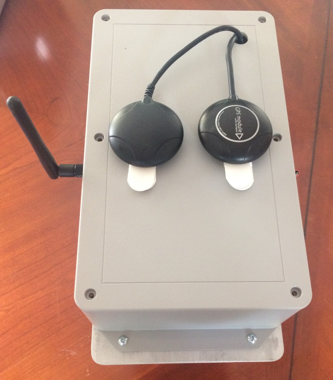
The two GPS receivers mounted on top. The one on the right is a U-Blox NEO M8N, the left is a NEO 6M.
To mount the telemetry radio, I made sure to drill a hole in the thinner portion of the Polycase enclosure wall. These enclosures are injection molded (I think) and the walls are tapered so they can be removed from the mold easily. I mounted the radio by sandwiching the wall with the radio and antenna.
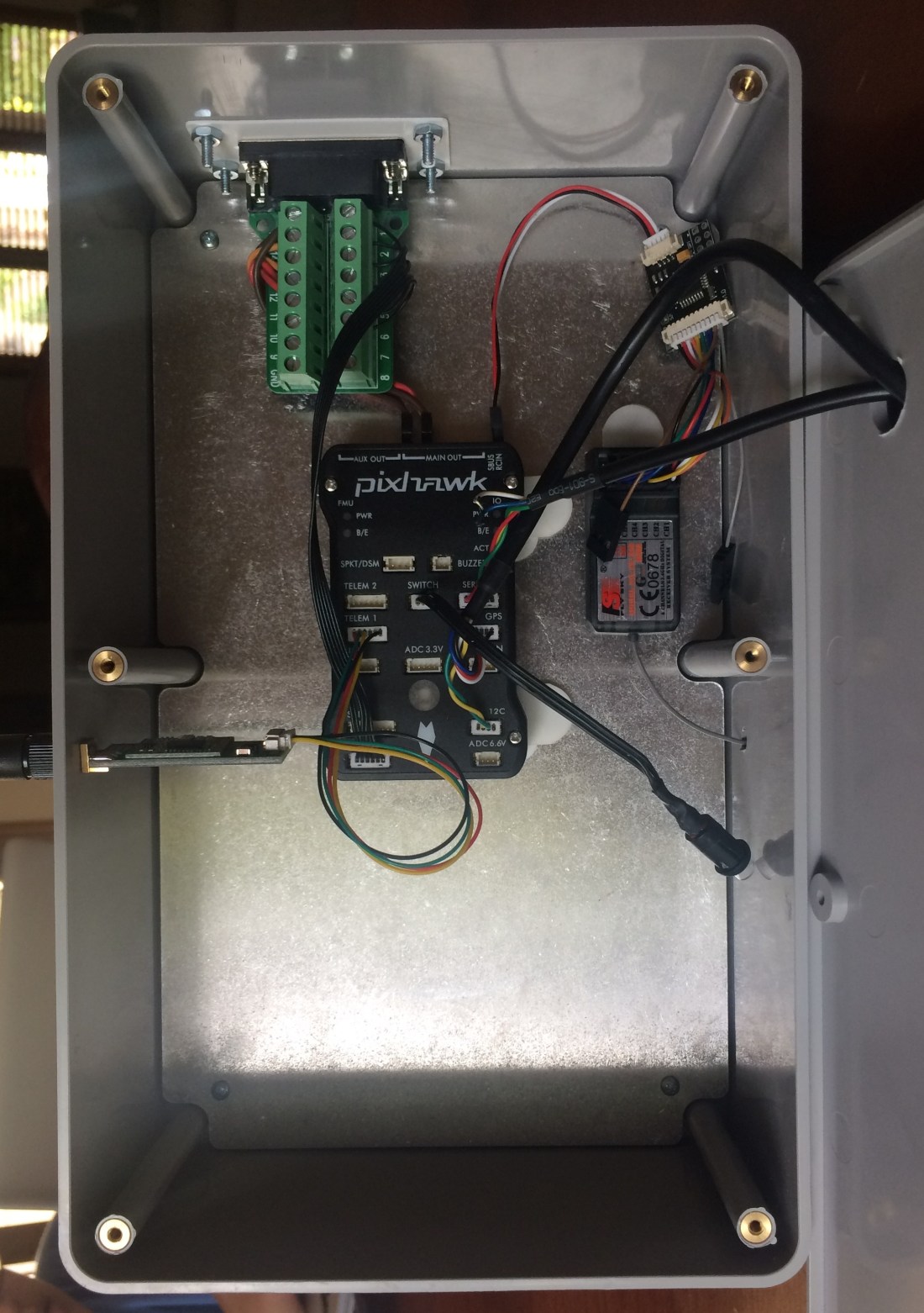
The control enclosure.
All that’s left is to put everything together on the wheel chair now.
Drawing wires in my CAD model was difficult work, but the effort paid off in spades when it came time to start wiring my enclosures. Doing this provided a huge advantage: I knew exactly how much wire I needed, not just the size, but down to the length, insulation color, even how much to strip off the ends.
Because of this, putting the power electronics enclosure together went quickly. I think I spent more time stripping and crimping wires than I did assembling components in the box. Below is a picture part way through construction.
The power electronics components. Things are starting to take shape.
I missed the fact that the Mauch current sensor only comes with 10cm long power wire leads. Because of this I had to use one of my 10 gage Posi-Locks to splice another wire so it could reach the toggle switch. Even a well thought out CAD model won’t prevent every mistake.
The completed power electronics enclosure mounted on the wheelchair chassis.
I was able to salvage quite a few bits and pieces from the old wheelchair wiring harness like the battery terminal boots and some nice pieces of 10 gage wire. I also ended up using the 16 gage Posi-Locks to connect to the motors. The wires were smaller than I modeled them.
I was a little bit paranoid about getting all of my connections right, so before I connected the wires to the battery terminals, I did a lot of bench testing with my multimeter. Having modeled up my wiring in the CAD program I had a good idea of what things should have continuity between them and what things shouldn’t. Once I was satisfied that everything was wired up properly I connected the battery terminal wires.
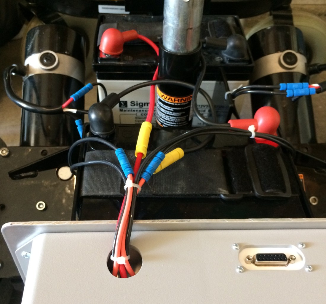
The wiring to the battery terminals and motors. The Posi-Locks make for an excellent connection, but you have to strip the wires to just the right length.
With the wires connected and in place, I put some zip ties around them to clean things up. There were some convenient holes in the wheelchair chassis that I used to secure them to.
At this point, all that was left was to make sure the Sabertooth and Mauch BEC power up properly. So I flipped the switch up, and to my surprise everything seemed to work.
The Sabertooth lit up and the fan came on briefly. The Sabertooth BEC measured 5V as it should. A blue LED on the Mauch current sensor came on. The voltage across the Mauch BEC measured 5.30V on the money.
With the power enclosure complete, all that’s left is the control electronics enclosure…
The XLR charger came in the mail today. I was a little worried because it was advertised as 24V output and after I bought it I realized that you really need something like 28V to charge a 24V lead acid battery. The 12V float charger I have is actually 15V at 150mA.
The charger was advertised as being used to charge electric wheelchair batteries though, so I didn’t worry too much. I checked the output voltage and it came it at 27.3V. Not too bad.
The charger label.The actual output is 27.3V.
The connection between the panel mount XLR and the charger was a little disappointing though. It’s tight. Really tight. I’ve been trying to break it in, but I may have to take the panel mount apart and grind down the poka-yoke feature. Just enough to let it slide on though, not enough to remove it completely. It’s there for a reason.
Polycase (the guys I bought my enclosures from) advertises their epic machining capabilities on their website. They sent me a sample free of charge and I was quite impressed. So before I ordered my enclosures, I used their quote wizard to see what it would cost to machine the enclosure and the mounting panel.
The numbers I got back were astronomical, partly because I was only buying two enclosures, both with different cutouts. The cost shoots up fast for each additional side of the enclosure you need to machine. I had four sides I needed machined on one box, so the quote came back in the neighborhood of $200. For $200, I can afford to drill my own holes and make my own cutouts.
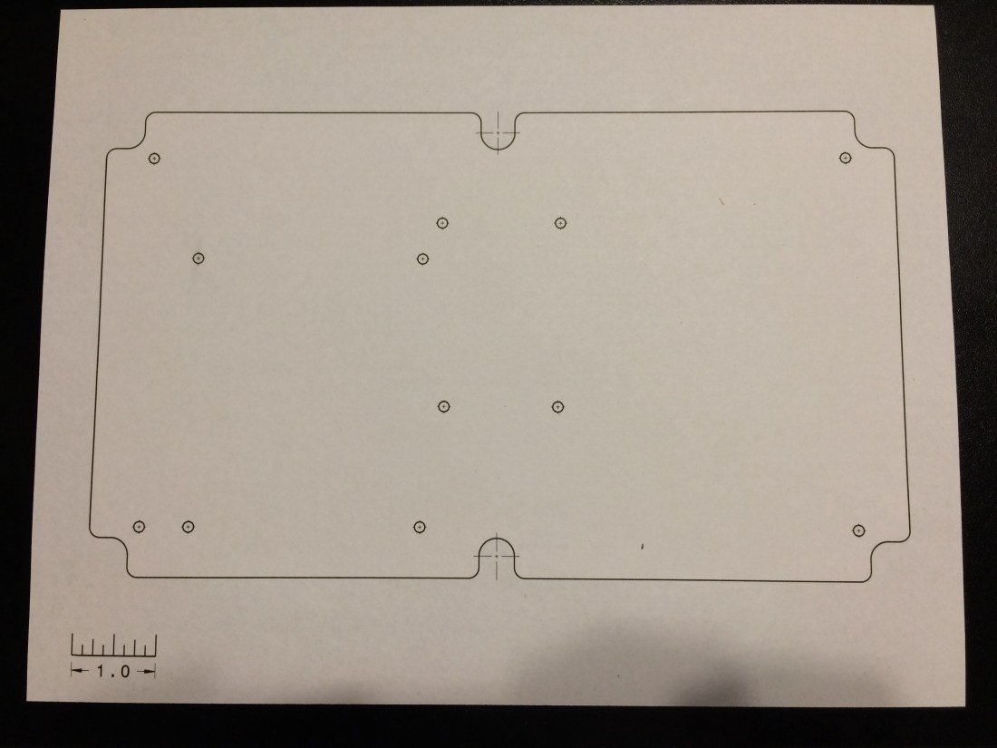
But how do you make sure you drill everything in the right place? The answer: paper plots!
The paper plot for the power electronics enclosure mounting panel.
If you drew your parts up in a CAD program and made them dimensionally accurate, you can make a paper plot in no time flat. Even if you didn’t, you can draw up something in a 2D CAD program and make one using a similar process:
Make a drawing of your part that contains the features you need to cut.
Include a feature of known length. In my paper plot I put a scale in the corner, but you could use a feature on the part if you know it’s length.
Scale the drawing 1:1.
Print it off.
Physically measure the feature mentioned in (2) and ensure it measures accurately.
Trim the paper plot and tape it to your part, positioning it appropriately.
Use the paper plot to establish your hole locations!
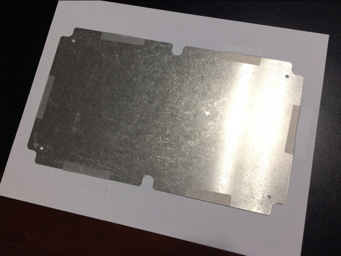
It’s really as simple as that. I held the panel piece over my paper plot and aligned the edges with the lines on the paper. I recommend lots of tape because you don’t want things moving, especially after you’ve drilled a few holes.
Use lots of tape: you don’t want the paper plot moving after you’ve drilled half your holes!
I recommend overlaying your parts with holes on the paper plot to make sure they actually align the way you expect. The DXF file for the current sensor mount did not align with the actual part I received. Measure twice, cut once is good advice to live by.
Pro-tip: add cross hairs on every hole feature you plan on drilling. This will give you something to align your drill bit to. Another good idea is to actually put a diameter dimension on your holes, so you use the right drill bit size. I had to go back and check my CAD model to see what size I needed.
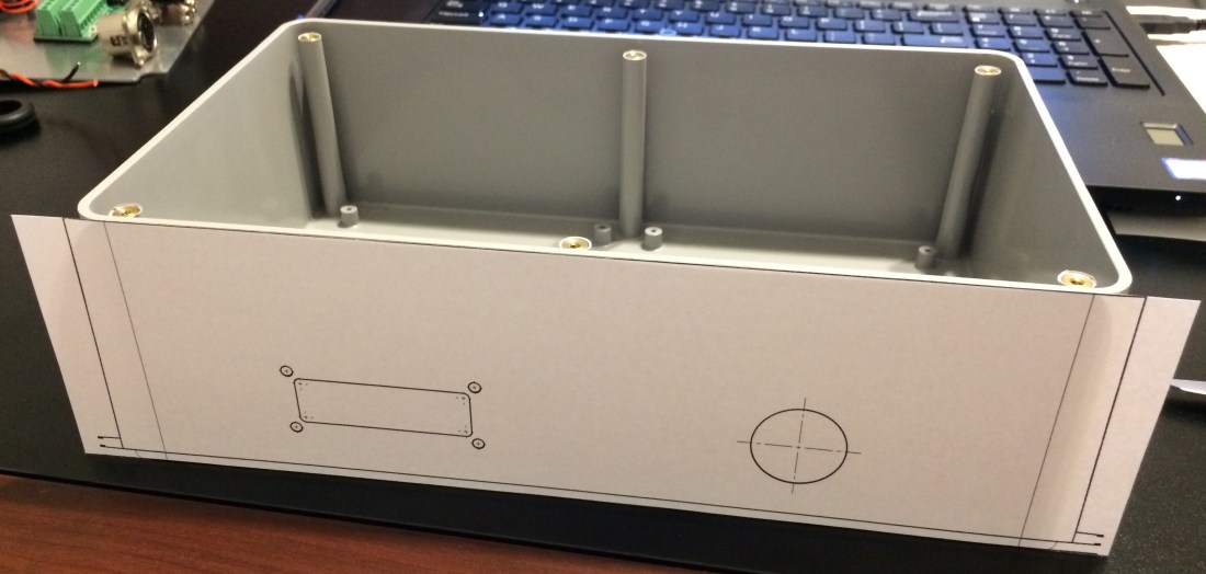
The paper plot for one of the enclosure sides.
You can use this process for just about anything. I also made paper plots for the enclosure itself. I could have used a paper plot to drill holes into the wheel chair frame, but if you have the mating part on hand, it’s better to use that, especially for items whose fit is critical.
I have a confession to make. I’ve been making the machinists I work with drill some large hole diameters through some pretty thick steel. I didn’t think it was a big deal at the time, but I now know better. It’s kind of painful. Literally.
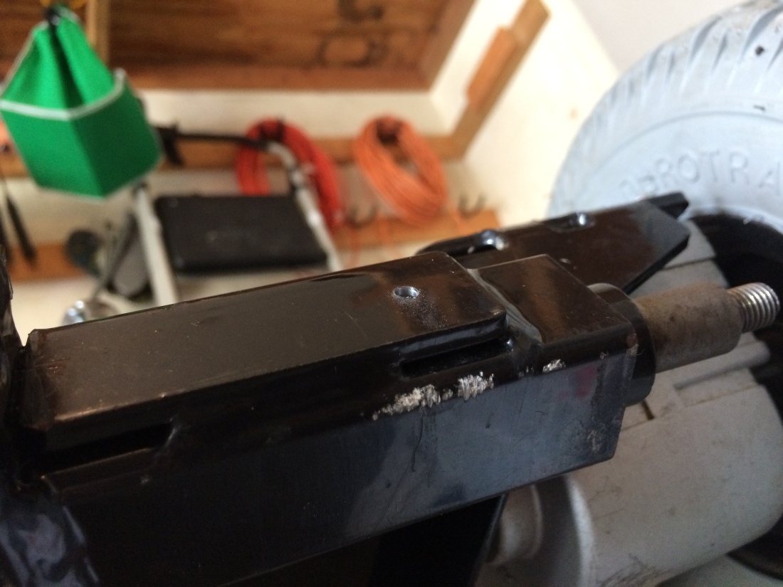
For mounting the power electronics box to the wheel chair chassis, I had to drill two 0.25in diameter holes through a piece of 1.5in X 1.5in steel tube. No big deal, I’ll just start out with a 0.125in drill bit and go from there.
Generally that wouldn’t be too bad of an idea, if it was actually a steel tube. The ends were plugged with some kind of threaded stud to mount the foot rest for the wheel chair. As I started drilling through the tube I quickly realized that this was actually a solid piece of bar stock.
The first 0.125in diameter pilot hole. It only took 30 minutes!
To make matters worse, I really didn’t have any sharp drill bits, just some old ones I bought at a garage sale years ago. It helps to have sharp bits if you’re going to drill through 1.5in thick steel.
I clamped the mounting plate to the chassis and started my first pilot hole using the plate as a template. Once I had a nice dimple in the frame I removed the plate and kept drilling.
About 5 minutes in my arms were killing me. The wheelchair is pretty heavy, but I still had to brace it with my left arm to keep it from rolling off the blocks that raised it to where I could get the drill on it. And my right arm started aching from pushing the drill into the wheel chair.
I knew I should drill slowly: too many RPMs and you will heat up the drill bit and dull the cutting edge. But even going slowly I wasn’t making much progress. I tried not to apply too much pressure to the drill either, but without it, it wouldn’t make any chips at all.
I did some reading and discovered that using some cutting fluid can allow you to drill at higher RPMs, so I borrowed some non-stick vegetable oil spray from the pantry and sprayed the bit and the hole with it. That seemed to help, but not much.
In the end it took about an hour for each of the two holes, starting with a 0.125in bit, moving to a 0.1875in bit and finishing with a 0.25in bit. I can’t tell you how satisfying it felt when the drill lurched forward as it broke through the back side of the bar stock.
So machinists everywhere: I’m sorry for all the holes I’ve made you drill in steel plate. I will at least have a very good reason the next time I ask you to do it. I understand (in a small way) your pain.