Polycase (the guys I bought my enclosures from) advertises their epic machining capabilities on their website. They sent me a sample free of charge and I was quite impressed. So before I ordered my enclosures, I used their quote wizard to see what it would cost to machine the enclosure and the mounting panel.
The numbers I got back were astronomical, partly because I was only buying two enclosures, both with different cutouts. The cost shoots up fast for each additional side of the enclosure you need to machine. I had four sides I needed machined on one box, so the quote came back in the neighborhood of $200. For $200, I can afford to drill my own holes and make my own cutouts.
But how do you make sure you drill everything in the right place? The answer: paper plots!
If you drew your parts up in a CAD program and made them dimensionally accurate, you can make a paper plot in no time flat. Even if you didn’t, you can draw up something in a 2D CAD program and make one using a similar process:
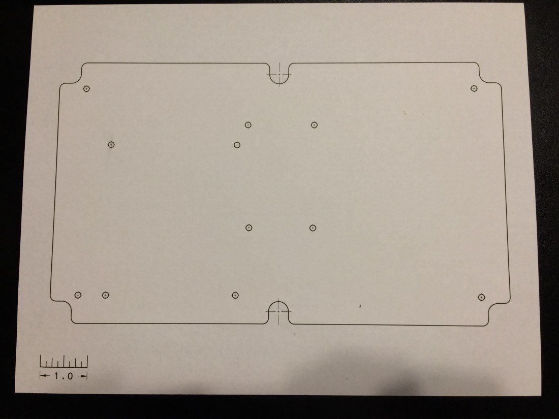
- Make a drawing of your part that contains the features you need to cut.
- Include a feature of known length. In my paper plot I put a scale in the corner, but you could use a feature on the part if you know it’s length.
- Scale the drawing 1:1.
- Print it off.
- Physically measure the feature mentioned in (2) and ensure it measures accurately.
- Trim the paper plot and tape it to your part, positioning it appropriately.
- Use the paper plot to establish your hole locations!
It’s really as simple as that. I held the panel piece over my paper plot and aligned the edges with the lines on the paper. I recommend lots of tape because you don’t want things moving, especially after you’ve drilled a few holes.
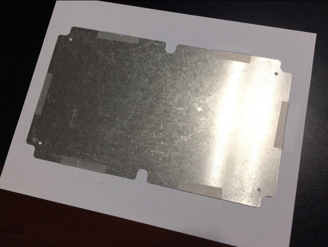
I recommend overlaying your parts with holes on the paper plot to make sure they actually align the way you expect. The DXF file for the current sensor mount did not align with the actual part I received. Measure twice, cut once is good advice to live by.
Pro-tip: add cross hairs on every hole feature you plan on drilling. This will give you something to align your drill bit to. Another good idea is to actually put a diameter dimension on your holes, so you use the right drill bit size. I had to go back and check my CAD model to see what size I needed.
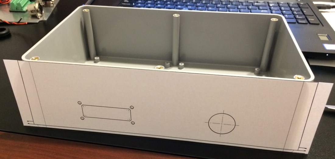
You can use this process for just about anything. I also made paper plots for the enclosure itself. I could have used a paper plot to drill holes into the wheel chair frame, but if you have the mating part on hand, it’s better to use that, especially for items whose fit is critical.
