Drawing wires in my CAD model was difficult work, but the effort paid off in spades when it came time to start wiring my enclosures. Doing this provided a huge advantage: I knew exactly how much wire I needed, not just the size, but down to the length, insulation color, even how much to strip off the ends.
Because of this, putting the power electronics enclosure together went quickly. I think I spent more time stripping and crimping wires than I did assembling components in the box. Below is a picture part way through construction.

I missed the fact that the Mauch current sensor only comes with 10cm long power wire leads. Because of this I had to use one of my 10 gage Posi-Locks to splice another wire so it could reach the toggle switch. Even a well thought out CAD model won’t prevent every mistake.

I was able to salvage quite a few bits and pieces from the old wheelchair wiring harness like the battery terminal boots and some nice pieces of 10 gage wire. I also ended up using the 16 gage Posi-Locks to connect to the motors. The wires were smaller than I modeled them.
I was a little bit paranoid about getting all of my connections right, so before I connected the wires to the battery terminals, I did a lot of bench testing with my multimeter. Having modeled up my wiring in the CAD program I had a good idea of what things should have continuity between them and what things shouldn’t. Once I was satisfied that everything was wired up properly I connected the battery terminal wires.
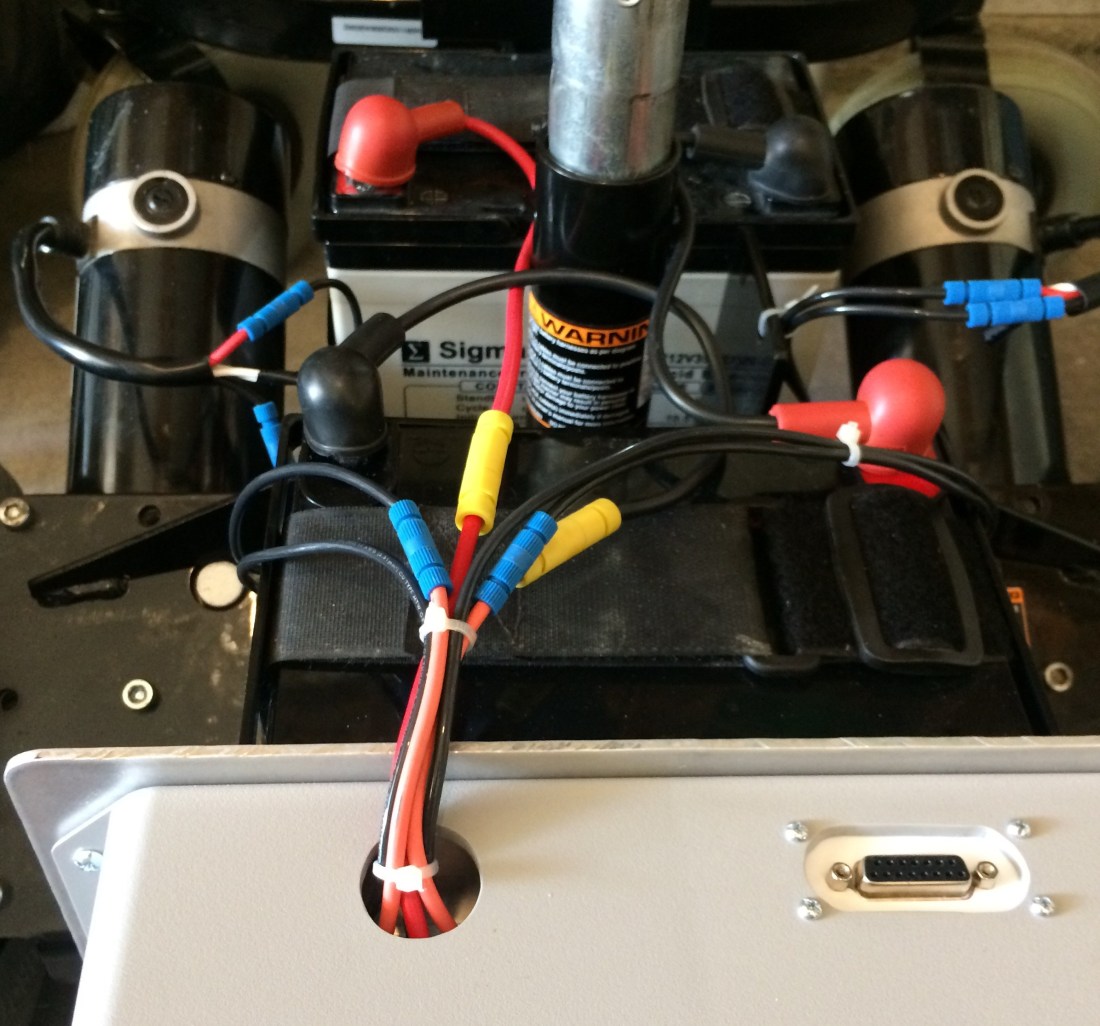
With the wires connected and in place, I put some zip ties around them to clean things up. There were some convenient holes in the wheelchair chassis that I used to secure them to.
At this point, all that was left was to make sure the Sabertooth and Mauch BEC power up properly. So I flipped the switch up, and to my surprise everything seemed to work.
The Sabertooth lit up and the fan came on briefly. The Sabertooth BEC measured 5V as it should. A blue LED on the Mauch current sensor came on. The voltage across the Mauch BEC measured 5.30V on the money.
With the power enclosure complete, all that’s left is the control electronics enclosure…
