One of the painful experiences I had on rover V1 was getting the motors to turn the correct way. It sounds simple enough, but there are several different variables that control motor rotation direction and behavior:
- Motor wiring polarity. How you connect the two wire leads on the motor into the Sabertooth motor controller affects rotation direction.
- DIP switches on the Sabertooth motor controller. There are 6 on-off switches on the Sabertooth that determines how it interprets RC input from the Pixhawk.
- Servo output from the Pixhawk. There are 8 servo outputs on the Pixhawk. These must be assigned to the correct output function.
- PPM encoder wiring. My RC receiver has 6 RC outputs, but there is only one RC input on the Pixhawk. I use a PPM encoder to mix the six channels into one. Depending on the wiring configuration into the PPM encoder affects which RC channel gets associated with yaw, roll, pitch, etc.
- Mission Planner servo reversing. You can reverse the RC input in Mission Planner.
- Skid Steer settings. This rover turns by varying the rotation speed of the left and right motors relative to each other. There are a settings related to this behavior.
- RC mapping. Which stick on the RC transmitter should control throttle or steering? There’s settings for that, too.
Pretty straightforward, right? This post is for my own personal recollection of this process in case I lose my settings or have to rebuild the rover for some reason. But hopefully I can also shed some light on how to wade through this mess of options and get your rover behaving as desired.
Step 1: Put your rover up on chocks
Seriously, get those wheels off the ground. We’re doing this exercise because the wheels don’t turn the right way. In the wise words of Robby, “your shins will thank you“.
Step 2: Preliminary Wiring
You gotta start somewhere, so don’t worry too much about getting all the wires set up correctly on the first try. Something is going to be backwards or configured incorrectly in Mission Planner. Here’s my checklist for preliminary wiring:
- RC receiver is plugged into the RC slot of the Pixhawk servo rail.
- Channels 1 and 3 of the Pixhawk output have servo wire running to the RC input terminal block on the Sabertooth (these are the defaults in Mission Planner).
- Motors are wired into the motor output terminals on the Sabertooth.
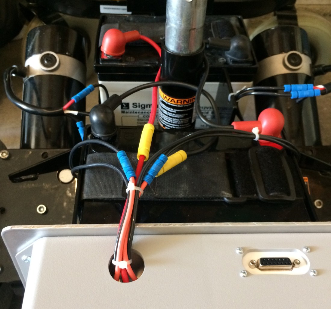
- Batteries and BEC are all wired appropriately.
Double check your wiring to make sure your battery or BEC is wired properly and with the rover on chocks, turn on the power.
Step 3: Sabertooth DIP switches
Dimension Engineering has an excellent wizard to help you get your DIP switches configured properly. You’ll obviously need to select what’s appropriate for your situation, but for mine I selected the following:
- Lead acid battery chemistry
- Simulated RC signal
- Independent mode
- Exponential control
Regarding (4), you could probably do linear control too, this is a preferential thing I think. The rest of these settings are mandatory as far as I can tell.
The bottom line here is that we want the Pixhawk to mix the steering and throttle signals for skid steering, not the Sabertooth. I’m pretty sure this is why (3) above is set to independent mode. If it wasn’t, you’d have the Pixhawk mixing the signals, and then the Sabertooth mixing them again. Quite the mess, I’d imagine. Probably one of the many things that went wrong on rover V1.
This should result in the following DIP switch configuration:

Step 4: Ensure Your Motors Are Responsive
Flip on the RC transmitter, arm the Pixhawk with the push button switch, and move the sticks around. The motors should at least respond to RC input on the transmitter, even if it seems completely jacked up. If not, go back to step 2 and check your wiring. Motors kicking straight into high gear with the sticks in the neutral position shouldn’t be unexpected at this point. This is also why step 1 is very important.
Step 5: Tweak Some Mission Planner Settings
According to the Ardurover documentation, you’ll want to set the following parameters in Mission Planner:
- SERVO1_FUNCTION = 73 (This sets servo 1 output to left motor throttle)
- SERVO3_FUNCTION = 74 (This sets servo 3 output to right motor throttle)
In recent versions of Ardurover I think this is all you need to do to enable skid steering. As always, refer to the most recent documentation.
Step 6: Get your RC transmitter mapped correctly
Decide how you want your RC transmitter to control your rover. I have an airplane style transmitter and so I wanted steering and throttle both on the right hand stick. There were a few reasons for this:
- When you release the stick it returns to the center neutral position, which will stop the rover.
- You can go forward and reverse on this stick. The left stick zero position is all the way down as it’s supposed to be throttle for an airplane, so there’s no way to go in reverse if you assign throttle to this stick.
- I can control the rover with one hand and use my left hand for something else.
You’ll want to assign throttle and steering to your desired stick motions in Mission Planner using the RC mapping parameters. In my case you’d go with the Ardurover default:
- RCMAP_ROLL = 1
- RCMAP_PITCH = 3
This sets your roll and pitch transmitter signals to your the appropriate Pixhawk output.
Step 7: For PPM Encoder Users…
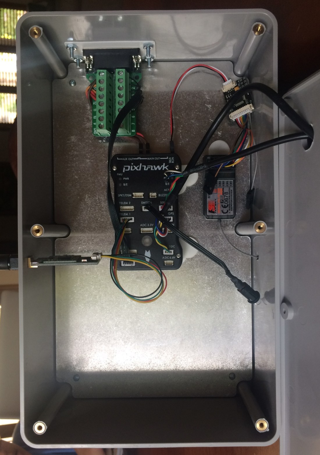
So you cheaped out when buying your RC transmitter? You’re among good company. Your setup will probably look something like this:

PPM encoder users have another layer where they can improperly assign RC channels. Roll might be channel 1 on the transmitter and properly assigned on the servo output of the Pixhawk, but PPM encoder users will need to make sure that Mission Planner shows the Pixhawk as interpreting roll as channel 1.
Pull up the radio RC transmitter configuration page under Initial Setup in Mission Planner and verify that the RC mapping is correct. If it isn’t, you’ll need to fiddle with the way the PPM encoder is wired so that the channels map across.
Step 8: Play With Settings
Now you’ll want to watch the motors as you move the RC transmitter sticks. Forward should obviously cause both motors to rotate in the same direction. Right should cause the motors to counter rotate; same thing with moving the stick to the left. Make sure you check all stick positions so that there’s no funky-ness with the full range of motion.
Are the motors still doing something strange? Now is when you can adjust the motor wire lead polarity. Hopefully you can identify one motor that is behaving opposite how it should. If this is the case, flip the motor wires on that motor and see how this affects things.
Step 9: Document Everything
Did you get it working? Save those parameters. And take pictures of everything, the Sabertooth DIP switch settings, the wire runs, the PPM wiring. Everything. Better yet, take a video of it while you explain verbally what you did to get it to work. You’ll thank yourself later.
Still having trouble? Did you reverse any servos? I thought that servo reversing would be a good idea to get things to work, but I really advise against it. You might get things configured to where your rover does run correctly in manual mode, but when it comes time to throw it in auto, that servo reversing can make things very weird. best to switch wires around instead in my opinion. Get everything configured in the hardware and leave the software at the default settings.
One last word about Mission Planner settings: don’t push buttons. Normally I like to push buttons until something works, but Ardupilot is one of those situations where it really doesn’t help and usually makes things worse.
There are literally hundreds of parameters to play with, and even if all of the settings I’ve described here are correct, there could be a phantom parameter somewhere you tweaked that is messing with your setup. If you didn’t heed this advice you may be better off resetting the parameters to their default.
Step 10: Field Testing!
But that’s for another post. Stay tuned!